I was trying to figure out a project for some 955s I have laying around. The spice model of this simple DC coupled cathode follower shows a cancellation of 2h depending on the load. I can't figure out why that would be happening. Do you think it is just some quirk of the model or if it is something I might be able to exploit in the actual build?
Thanks,
Marty
Thanks,
Marty
Attachments
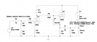
The latter 9002 generates higher 2nd harmonic at 10 k load than at 100k load, obviously.
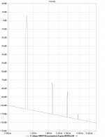
And it happens to be so, that at 10k load the amplitudes of 2nd harmonic produced by 1st and 2nd stage are nearly the same, but 180 degrees out of the phase and therefore the 2h distortion is mostly canceled as your simulation demonstrates.
This is the most typical distortion canceling action (that some designers utilize even today).
It makes sense once noted.
Imagine input goes positive. U1 current goes up. U2 current goes down. The changes of Gm are opposite.
U1 runs with small NFB. U2 nominally runs with large NFB. You expect U1 to rise toward 2%THD at very high levels, while U2 will probably never get even 0.5%THD.
BUT. You tried U2 load of 100K (33K total) and 10K (8K total). At the low Z, U2 is working very hard with less NFB. It will distort more. Being nominally in opposition to U1's distortion, there will be some cancellation.
{EDIT: or, what artsalo said.}
There probably is a "0.000000%" null, for a single harmonic, at a specific level and a specific load. Variation of load will quickly take a lot of zeros out of the THD number. Variation of level (this is speech/music work) will also shift off the null. The higher order components probably won't cancel at the same point (if they do, the model is too simple for a real tube). Intermodulation distortion will reduce around the THD null, and for simple test tones may be quite low. For many-many-tone signal (music) there will be IM of IM products and a haze of low level non-harmonic hash (as in all amplifiers); but near the null this may be lower. Variation of DC operating point (tube drift) will also shift off the null.
But hey, it is an easy test. Build that thing, with a 100K Audio pot load. Beat it on test bench and listening room. Simple tones and complex orchestral works. Does turning the pot around the 10K zone improve the sound? (Beware aural effects of C1 size shaving bass at low loads; also we pick caps "large" to reduce their distortions in-circuit so you could wind up balancing one against another.)
Last edited:
It's the nature of the beast. The 2nd harmonic generated by fundamental driving the first stage is out of phase with the 2nd harmonic generated by fundamental driving the second stage. With two stages identical in topology, input level and loading the cancellation is ideally complete.
-
-
Attachments
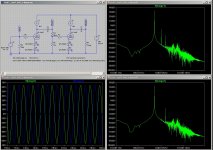
As usual what is unexpected for me is explained in short order around here. The model seems to work as PRR suggested it would above. I did not hunt for specific nulls but the levels of different harmonics changed as the load was varied. A pot on the output seems like it would make a fun control for the front of a preamp, a guy could fiddle with something like that for hours ")
I tried a couple of things from the Broskie article in model space. The positive feedback from cathode to cathode and adding the resistor above the second stage. Neither seem like good trade offs to me but I am probably missing something. I think the CF output needs a regulated or well filtered supply anyway so I didn't spend much time thinking about matching the current draw between stages.
Thanks again
...I think the CF output needs a regulated or well filtered supply anyway...
The voltage-amp stage has a PSRR of about 1/3.
The CF would tend to a PSRR of about 1/Mu, like 1/25, though heavily loaded it will be worse.
The 1st stage needs more filtering than the CF.
As both stages are fairly thrifty, and large electrolytic caps are now cheap, I could see running both on one node.
- Status
- This old topic is closed. If you want to reopen this topic, contact a moderator using the "Report Post" button.
- Home
- Amplifiers
- Tubes / Valves
- unexpected harmonic cancellation