Guys,
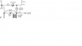
What's the purpose of 87 ohms resistor in series with VR tube in Raven preamplifier power supply ? See schematic below.
It looks like it raises output impedance by 87 ohms. I'd say it woudl work better without it.
Let me know
Thanks
Gurevise
What's the purpose of 87 ohms resistor in series with VR tube in Raven preamplifier power supply ? See schematic below.
It looks like it raises output impedance by 87 ohms. I'd say it woudl work better without it.
An externally hosted image should be here but it was not working when we last tested it.
Let me know
Thanks
Gurevise
Attachments
Last edited:
Hi gurevise,
And you would second guess an expert ... why?
The resistor probably prevents oscillation due to stray capacitance. VR tubes have a negative resistance portion in their characteristic curves. You wouldn't put capacitors directly in parallel with a VR tube, and the impedance of a CCS is so high that strays might be a problem. As drawn, it looks like a very stable design.
What happens if you put some capacitance in parallel with a VR tube? Depending on the circuit values, you get a "relaxation oscillator". You can make a neon lamp blink using these principles. A neon lamp is a form of VR tube but without controlled breakdown characteristics.
-Chris
Hi DF96,
I wouldn't bet on that. Look up the data sheet for the VR tube as they will spec what you can hang across it.
If you want to reduce the noise of these tubes, place a resistor between the tube and whatever is using the reference. Use a capacitor to ground on the side farthest from the VR tube. Yup, its a low pass filter.
-Chris
I found OD3 measurement data here:
Testing Power Supplies
It shows VR tube being highly inductive. I don't see how stray capacitance would cause any issues (oscillation) unless more than 0.1uF. Which is highly unlikely.
Dropbox - VR tube impedance measurement.JPG
Testing Power Supplies
An externally hosted image should be here but it was not working when we last tested it.
It shows VR tube being highly inductive. I don't see how stray capacitance would cause any issues (oscillation) unless more than 0.1uF. Which is highly unlikely.
Dropbox - VR tube impedance measurement.JPG
Last edited:
Trying to fix broken link to VR measurements
VR tube impedance measurement.JPG - Google Drive
An externally hosted image should be here but it was not working when we last tested it.
VR tube impedance measurement.JPG - Google Drive
Last edited:
Hi Magz,
You are so lucky!!!
All VR tubes have a negative resistance characteristic in their transfer function. Enough capacitance (0.1 uF is well into the danger area!) and you create a relaxation oscillator. This characteristic is used to flash neon lamps as determined by the resistance and capacitance. The VR characteristic supplies the gain (negative resistance, remember?).
Now as far as inductance and capacitance is concerned, what would you call an inductor and capacitor in parallel (from an AC point of view)? How about a tank circuit! These are used in oscillators as the frequency determining component. You need to learn more about components if you even remotely consider deviating from instructions.
-Chris
I hate to be a party pooper, but isn't the idea of a gas discharge tube to act as a reference to an active regulator? I mean … it can run at a near-constant current; it doesn't actively participate in the downwind variable demand for current; it can run at lower mean current so that it'll last a bunch longer. Dunno. Hi mu cathode followers make pretty-good constant voltage regulators. Pentodes better than triodes.
Just saying.
The snippet of schematic caused a nature of "long searches" to find the right matching schematic. For some reason, the designer insists on using a number of home-made conventions for positioning components in the diagram. "Artsy" without added value. But I'm just cranky this morning. Afternoon.
GoatGuy
I found OD3 measurement data here:
Interesting technique to put the resistor in series with the bypass caps:
Attachments
I have always used a 100 ohm resistor, both for the above reason, and also a very simple way of measuring shunt current. 0.068uF cap has never been problematic; I could try increasing to 0.1 but never found a reason to. Noise has been effectively immeasurable w.r.t. the output signal, and regulation characteristic has minimal requirements when used in PP amp. It simply helps set the operating point of the rest of the circuitry. Wouldn't use it in a SET.
Hi GoatGuy,
Yes, a VR tube is like a zener diode. You actually do want to run some current through them and they tend to last a long, long time.
If you get the right capacitance across the VR tube, you can get it to strike, extinguish and strike again ... on and on. Probably rough on the tube. A CCS feeding the VR tube really expands the trouble area with capacitors since there isn't any resistance to damp anything from the charge side.
If you want to experiment, grab an NE-2 neon lamp (it's just as much a VR tube as the 5651 and others mentioned). Make sure your DC supply is above the strike voltage (~90 V) and use a resistor in series. Then place various capacitors in parallel and see what happens. I used to do this as a kid.
The biggest difference between an NE-2 and VR tube is that the NE-2 runs at much lower current and isn't shielded against ambient light (photons reduce the strike voltage). Aside from the uncontrolled dimensions and element placement, it is the same. Probably not the best idea to use one that way (as a VR tube). I may be wrong, but I think the minimum recommended current is around 5 mA and up to 25 mA or so for most VR tubes.
-Chris
The gas tube (or a Zener) isn't about a near-constant current. If it did that, we would not need it. It takes the -difference- between power source current and load current. Either or both may vary (our "problem"). The gas/Zener will take more or less current, trying to keep its Voltage constant.
The NE-2 is a reasonably useful reference. It is NOT tightly specified so you don't know quite what voltage you will get. A "jumpy" plasma does not hurt the light function but may give erratic regulation. And they are light sensitive, but we have duct-tape.
All the plasma "arc" processes WILL oscillate with some value of parallel capacitor, supply voltage, supply impedance. Negative Resistance isn't an easy date but an oscillator waiting for provocation.
NE-2s were reliable enough as semi-constant sources and as oscillators that H-P used one (or two!) as the built-in calibration source for some of their oscilloscopes.
I had never heard of a plasma being "inductive". If you plot an inductance on that same graph, it rises with frequency, but much less than a pure inductance. This makes sense. It is not "loose" charges sloshing around, but relatively heavy and lossy ions limiting the slosh.
Attachments
- Status
- This old topic is closed. If you want to reopen this topic, contact a moderator using the "Report Post" button.
- Home
- Amplifiers
- Tubes / Valves
- Q VR tube regulator in Gary Pimm designs