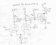
A DC coupled two stage PSET amp:
- SRPP front end with 1/2 6CG7 for upper tube and EF80 for lower tube per channel, with screen grid feedback taken at the output of the transformers. This allows for triode operation of the pentode with the output stage in the loop. "Triode connected" EF80 and 6CG7 have rather similar plate resistance which allows, along with bipolar PS, for very good PSRR.
- parallel 5687 (two tubes per channel) output stage, directly coupled with the input stage. The reference of this stage is the 0V line.
- bipolar PS allowing, along with DC controlled SRPP. for real DC coupling and correct bias of the output tubes with no automatic bias whatsoever.
- passive (resistive) DC servo for bias control by the input stage.
The project currently on test (see the terrible photo !) is an attempt to find an alternative to 2A3 set amps : a couple of 5687 (4 triodes) shows rather superior figures than a 2A3 on the paper: lower plate resistance, greater transconductance, lower stray capacitance, lower distorsion, far lower input signal amplitude for full output, lower price, identical max power. The only apparent drawbacks are larger heater power requirements and a pathetic look when compared to the 2A3.
OK then, I gave it a try along with the bipolar DC coupled topology and pentode-triode SRPP - screen grid feedback I've been using for some time now in my amps.
I currently use the amp for mid and trebble for my biamped KLIPSCH HERESY III and I try and compare it with my classic 6B4G amp (OK, not a true 2A3 amp!).
The bass drivers of the speakers are fed by a DC coupled two stage hybrid 10 W class A amp.
This amp is described on the french (sorry) site OTARION AUDIO. You can find there the very simple schematic diagram (audio section only).
I think it's worth testing 5687s instead of 2A3s on any SET amp, provided correct changes, especially bias, are made.
https://static.wixstatic.com/media/...99a7bfebf8336b579d~mv2_d_4000_3000_s_4_2.webp
I could not get anything to come up from the link.
The idea of using the screen grid of the input tube for N Fdbk is interesting. Should tend to make the amplifier emulate the internal triode there, if the loop gain is sufficient. I have seen a schematic for a P-P amplifier using this technique some while back, but could never find the link to it again.
Another similar approach is like below:
M1 could be a pentode or triode too.
The more gain in the loop the better the emulation of V1. V2 could be a pentode for more gain.
Attachments
That's all interesting, but my browsers (IE, FF, GC) have no idea of WTH the ".webp" link is. .. had zero luck with opening that.I think it's worth testing 5687s instead of 2A3s on any SET amp, provided correct changes, especially bias, are made.
https://static.wixstatic.com/media///blah-blah///_4000_3000_s_4_2.webp
"my ear" sense qualified 5687 as a somewhat harshy-sounding one. .. very possibly one might like it but no go to me. Have completed a project on these, so next time. .. will just go 2A3 ))
The interesting part is the PSET part, have this spinning in my mind for couple months. Just recently someone posted PSET on a KT-88s pair running conservatively, gonna try this.
Thanks for the fixed link.
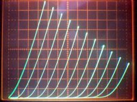
The 5687 curves look fairly similar in shape to the 2A3 curves, just different scale parameters. Four sections in parallel would seem a good match for the 2A3. The sound depends on the load line.
The screen grid N Fdbk will re-enforce the 5687 triode curvature and lower the output Z. More N Fdbk (more loop gain) would lower the output impedance further.
Getting low Z output with SETs is a frequent issue, and this solves that without squashing the triode sound.
Might want to scope out the triode curves of the EF80 to see how well they match the shape of the 5687 and 2A3 curves. More 5687 in parallel would lower the loading on each of them, possibly improving the sound. Curve tracer matching of the parallel 5687 would likely help too.
Last edited:
Found some curves for EF80 in triode.
http://www.tiffe.de/roehren/ef80pentode_as_triode.pdf
Rather a bit much "roll-over" in those curves. 2A3 does not have that much.
http://www.tiffe.de/roehren/ef80pentode_as_triode.pdf
Rather a bit much "roll-over" in those curves. 2A3 does not have that much.
Smoking-amp, could you elaborate this topology a bit with 6550 serving as M1 ? Wanna try it.The idea of using the screen grid of the input tube for N Fdbk is interesting. Should tend to make the amplifier emulate the internal triode there, if the loop gain is sufficient. <snip>
Or if, let’s say the driver is a twin 6939 tetrode, with the one’s plate fed from the UL OPT’s tap, makes sense?
Tnx.
Smoking-amp, could you elaborate this topology a bit with 6550 serving as M1 ? Wanna try it.
Sure. The scheme is using N Fdbk thru the V1 tube (inverted triode mode) to control the output. Looking at the current thru V1, that would be constant IF it's plate V were to vary at -Mu times it's grid V variation. Then no correction drive signal would be sent forward thru V2 via cathode current. Any variance however leads to the appropriate polarity correction.
With sufficient gain in V2 (could use a frame grid pentode here), M1 will be controlled in such a way as to insure very near compliance with the Mu ratio between V1 plate and grid V. So if V1 plate is equal to or scaled to the amplifier output, then output will be Mu x V1grid x (any resistive or UL scaling factor) with sufficient loop gain.
If M1 already closely conforms to the Mu characteristic of V1 (as Aboulafia's scheme approaches, then not much work is required by the inverted triode N Fdbk loop, except correcting for any loading effects)
So the scheme will work best if V1 and M1 have similar V gain characteristics. With -sufficient- gain, M1 can be anything that just works, N Fdbk rules the show (a frame grid tube at V2 !). Another benefit of the scheme will be considerably lowered output Z from the N Fdbk, since it is determined to match the Mu characteristic, regardless of loading.
Using a tetrode, pentode, beam ... for V1 allows one to use its internal Mu characteristic (N Fdbk to grid 2 then) in a similar way. Either by cathode current into a diff amp or plate current to another stage (like Aboulafia's).
Since V1 does not need to be high powered, one can select remarkably linear small triodes. 1J6 (Mu 20) or 1E7G (Mu 10) for example are quite nice for a cheap emulated triode. (1E7G used in triode mode)
The basic stage may require further gain in front for a practical amplifier input signal. And the scheme can be generalized to a P-P amplifier if it is designed fairly cleanly. (recommend a class A output or a class aB Twin/Crazy Drive configured for constant gm crossover)
The use of a high gm (and Mu or V gain for high loop gain) part for V2 helps insure that the tail voltage stays near constant, preserving the Mu ratio rule of V1 by near "freezing" the cathode V of V1. A lower gm device for V2 would mainly just allow some feedthru of the V1 grid signal to the tail V, which would be OK, but output loading effects will put another component there related to the output load. OK if that's just a linear resistor.
The tiny amount of actual output from V1's plate (getting to the real output thru any series attenuator), is in phase and agreement with the output, so is of a tiny benefit. (ie, just ignore it) But probably will confuse anyone servicing such a weird amplifier....
1E7G curves:
Attachments
Last edited:
- Status
- This old topic is closed. If you want to reopen this topic, contact a moderator using the "Report Post" button.
- Home
- Amplifiers
- Tubes / Valves
- 5687 PSET