Question about the power supply drawn by Banat (see post 6), I thought about using rectifier tubes, as mentioned before.
Could the diodes be replaced by high voltage vacuum rectifier tubes like the russian B1-0.1/30 (V1-0.1/30)? These are half wave rectifier tubes, this means 4 tubes would be required, when replacing each diode pair by a tube, or like drawn in the navy NEETS Docs
Navy Electricity and Electronics Training Series (NEETS), Module 6 - RF Cafe
Yes... 4 tubes means 20A at 5V... But we already reduced consumption by going SE")
They should be able to deliver the A at around 450-500VAC, they are said to be good for 400mA at 30kv.
It could be done by using the 2 serially connected Triad F3x Transformers, one supplying the plus rail and one the minus rail or using two separate Hammond 76VA filament Transformers for each rail with a 0.1R/20W resistor to reduce voltage from 6 to 5V.
Could the diodes be replaced by high voltage vacuum rectifier tubes like the russian B1-0.1/30 (V1-0.1/30)? These are half wave rectifier tubes, this means 4 tubes would be required, when replacing each diode pair by a tube, or like drawn in the navy NEETS Docs
Navy Electricity and Electronics Training Series (NEETS), Module 6 - RF Cafe
Yes... 4 tubes means 20A at 5V... But we already reduced consumption by going SE
They should be able to deliver the A at around 450-500VAC, they are said to be good for 400mA at 30kv.
It could be done by using the 2 serially connected Triad F3x Transformers, one supplying the plus rail and one the minus rail or using two separate Hammond 76VA filament Transformers for each rail with a 0.1R/20W resistor to reduce voltage from 6 to 5V.
The B-1-0.1/30 has a heater center tap for the drain of the rectified power, I think.
Claudio, the triad F-8X transformers a a good and valuable option to Hammonds 6V Versions.
I attached a small schematic for a PSU with B1-0.1/30 tubes, but forgot to draw bleeder resistors. C is around 50uF per tube.
Thomas
Claudio, the triad F-8X transformers a a good and valuable option to Hammonds 6V Versions.
I attached a small schematic for a PSU with B1-0.1/30 tubes, but forgot to draw bleeder resistors. C is around 50uF per tube.
Thomas
Attachments
The Midlife Crisis - My 833C Amp Build
May be worth reading this insane thread.
May be worth reading this insane thread.
To all transformer winding specialists, is anybody out there able to wind high quality SE OPTs with the following specifications:
2.5k primary, 4 + 8R secondary, 1200V+ at 0.7A, 20Hz-25kHz frequency range, 170-180W
5k primary, 2 + 4R secondary, 1200V+ at 0.35A, 20Hz-25kHz frequency range, 80W (2 OPTs primary used in parallel, secondary series)
7.5k primary, 1.3 + 2.6R secondary, 1200V+ at 0.24A, 20Hz-25kHz frequency range, 60W (3 OPTs primary used in parallel, secondary series)
Did I forget something?
Trannies should have a safety margin enabling safe use at voltage fluctuations and long run time
I am asking because Mr Ogonowski has never built this type of high voltage and ampere transformers yet and is not sure If he can meet the frequency requirement and safety requirement (I appreciate his open and honest communication very much, all people being that open can only be recommended). The large pp OPTs he built for my 6L6 wxt Quad amp are of outstanding quality.
The same might be with power trannies, primary 240V (!)
the following secondary voltages are required
- 2X 500-0-500V at 0.8A
- 2x 170-0-170V at 0.3A
- 2x 3.15-0-3.15V at 3A
- 2x 5.1-0-5.1V at 20A (!)
And chokes
4x 10H/450mA at 700V
2x 5-10H/700mA at 1200V
Thomas
Last edited:
I startet a separate thread to get names of potential suppliers for the high voltage high current power transformers, chokes and output transformers.
Custom wound high voltage high current OPTs, PTs and chokes needed
This might be a useful listing of suppliers for others too.
Custom wound high voltage high current OPTs, PTs and chokes needed
This might be a useful listing of suppliers for others too.
And it works.
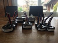
Tomasz from toroidy.pl is going to custom build the toroid power transformers
2 trannies 470-0-470V 800mA for the B+ supply and grid2 of the GU-46 and the voltage amp tubes
1 tranny 2x 170-0-170V 0.3A, 2x 3.15-0-3.15V 3A for the negativ bias and voltage amp tube filaments
2 trannies 5.1-0-5.1V 20A for the DC supply of the GU-46 filament
4 trannies 2x 2.5-0-2.5V 6A for the rectifier filaments
electrodump.nl supplies 2 8H 500/750mA 6.5kV chokes for the anode supply of the GU-46
The 4 10H 500mA 1000V chokes will be from Hammond (193Q), unbeatable for custom winders
This will already be about 70kg of Iron... Some additional kg will come from the large NOS 930uF/450V Nippon Chemicon caps, and the smaller 470uF/450V caps, the cirquit itself and the chassis (which will be made out of Industrial Aluminium profiles like in my last project
6L6 quad push pull monoblock project). This will again be a weight Monster...
Now it's all about the OPTs.
Last edited:
Back to the output transformers and the way to use the GU-46.
It seems to be difficult to get these large output transformers; i found two of transformer builders that said they are able to build these monsters, but it somehow did not seem to be reasonable; one does not say anything about frequency range, the other offers a range that seems to be far superior to anything else on the market... an this for single ended.
Does anybody have a proposal to run this tube at max. 100W single ended output, in a low distortion area with voltages around 1000V and max. 500mA as a pentode or triode, maybe including some NFB?
Thanks for your feedbacks
Thomas
It's been awhile, so let's refresh our memory, referring to GU-46 push-pull & single-ended amplifiers
You can run two 5k SE OPT's in parallel. The load line looks pretty reasonable and adding a bit of NFB, you should be good to go.
You can run two 5k SE OPT's in parallel. The load line looks pretty reasonable and adding a bit of NFB, you should be good to go.
Next steps
The project is currently in hold due to cost reasons, but I worked out a schematic using russian UHF triodes (GS-14, GS-4 or 6S17K as first step, GS-24B as second step) for amplification followed by a GU-46 in SE.
I found someone to build the OPT as 4.5k primary, 4, 8 and 16R secondary, so 2k primary is feasable by using the 8R as 4R.
Suggestions for the attached schematic?
Greetings
Attachments
- I think that you have reversed G1/G2 on GU46 power pentode ,
-both input and driver GS triodes obligatory need grid stopper resistor soldered close as possible to tubes grids ,
- I guess that that both GS tubes is self(auto) biased ?
--------------------------------------------------------------
btw , IMHO ideally(THD& musically wise) your SEP power amp need to be two stage based , not as is shown three stage based, with just one input and in the same time driver tube , but honestly I have no answer which tube will be the best choice for that purpose.?
Regards
Hi banat
You're completely right, grid 1 and 2 are reversed.
The triodes are filament biased.
I thought about using a two stage amplification section because the small GS tubes do not deliver enough swing to drive the GU-46. All of these triodes seem to be very linear in the voltages proposed.
I will have to test the best set up probably.
Thanks a lot
Last edited:
PSU question
Dear all
I am currently working in the PSU of the GU-46 SE amplifier.
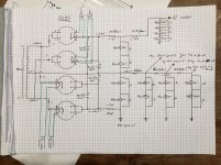
I decided to use 5C8S rectifier tubes, two in parallel per phase of the power transformer.
These Kenotrons have a rediculously small capacitor requirement, just 4uF for the first cap before the choke.
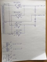
Now my question, is the following PSU setup correct (it is an adaption of Banats drawing). The point I am not sure of is the first caps connected to the paralleled Kenotrons, followed by the choke and a second set of larger caps and then one side to ground to lift the voltage in the CT.
A critical review would be appreciated.
Thanks a lot
Dear all
I am currently working in the PSU of the GU-46 SE amplifier.
I decided to use 5C8S rectifier tubes, two in parallel per phase of the power transformer.
These Kenotrons have a rediculously small capacitor requirement, just 4uF for the first cap before the choke.
Now my question, is the following PSU setup correct (it is an adaption of Banats drawing). The point I am not sure of is the first caps connected to the paralleled Kenotrons, followed by the choke and a second set of larger caps and then one side to ground to lift the voltage in the CT.
A critical review would be appreciated.
Thanks a lot
Attachments

Hi Thomas
-Your basic PSU design is OK , but I suggest you to add one 1N5408 diode series connected with each 5C8S rectifier tube , those SS diodes will act as protection,
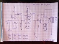
-make sure that by 5C8S tube pin 1&2 is K+(f) , pin 8 is only (f) , and pins 4&6 is anodes .
Best Regards
-Your basic PSU design is OK , but I suggest you to add one 1N5408 diode series connected with each 5C8S rectifier tube , those SS diodes will act as protection,
-make sure that by 5C8S tube pin 1&2 is K+(f) , pin 8 is only (f) , and pins 4&6 is anodes .
Best Regards
Attachments
Dear all,
attached you will find the schematics for the PSU's and for the single ended GU-46 amplifier (with a try for a variable NFB).
I am aware that my 3stage approach might lead to difficulties due to distorition etc. Nevertheless I want to try if it works, otherwise I will have to go back and take another round. I plan to bias the voltage amplifier triodes with resistors (heater bias level); but I am not sure if I calculated them correctly (R= heater voltage / heater current), i havent found anything helpful on the net about that.
And for the GU-46 filament, I would like to measure the Amperes of the tube; therefore I plan tu use a 1R resistor to ground; does that work (calculated this resistor would need to be 0.5R)?
Critical Reviews and Inputs would be very appricated.
Greetings, Thomas
Attachments
Last edited:
- Home
- Amplifiers
- Tubes / Valves
- GU-46 push-pull & single-ended amplifiers