Dear all
I am currently thinking about building a GU-46 push pull amplifier (two monoblocks).
As OPT I am thinking about a 5k Ohm 200W transformer, custom wound by ogonowski.eu, he already made several transformers for me. I am very satisfied with the quality of his work.
Can anybody comment in the impedance of 5k Ohm for a push pull OPT for a pair of GU-46? I have seen one other (russian single ended) project using a 5k OPT.
Intended anode voltage 1000-1100V (0.5A), grid 2 600V, neg. bias around -120V (to be evaluated).
I think about using the following set up for loading of the GU-46
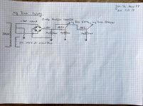
First stage: phase splitter 6SN7
Second stage: for each phase a 12hg7 voltage amp (something like pmillet)
Feed into GU-46
I plan to use coupling capacitors between each stage.
I have not yet decided on the PSU.
The high voltage cirquit for the GUs shall have its own transformer (approx. 800-0-800V 1.2A), the rest of the tubes shall fed by a smaller (approx. 350-0-350V 0.3A, 6.3V CT for the heaters).
The heaters for the GUs requires 8.3V at 16A for a pair (will need to be decoupled in pp) coming from an LED Power supply most probably. The negative bias will have its own transformer (approx. 100V 0.3A).
I would love to use paralleled mercury rectifier tubes for the high voltage rectifier, but this would need additional iron. Alternatively the use of bridge rectifiers at 1600V/30A or so could be used. The lower voltages shall be rectified by one 5U4G per block and the neg. bias by diodes.
I have not yet drawn a schematic, but would be very interested in your professional feedbacks. This Project is a bit bigger than all I did before, early Input is very welcome.
Greetings from Switzerland.
Thomas
I am currently thinking about building a GU-46 push pull amplifier (two monoblocks).
As OPT I am thinking about a 5k Ohm 200W transformer, custom wound by ogonowski.eu, he already made several transformers for me. I am very satisfied with the quality of his work.
Can anybody comment in the impedance of 5k Ohm for a push pull OPT for a pair of GU-46? I have seen one other (russian single ended) project using a 5k OPT.
Intended anode voltage 1000-1100V (0.5A), grid 2 600V, neg. bias around -120V (to be evaluated).
I think about using the following set up for loading of the GU-46
First stage: phase splitter 6SN7
Second stage: for each phase a 12hg7 voltage amp (something like pmillet)
Feed into GU-46
I plan to use coupling capacitors between each stage.
I have not yet decided on the PSU.
The high voltage cirquit for the GUs shall have its own transformer (approx. 800-0-800V 1.2A), the rest of the tubes shall fed by a smaller (approx. 350-0-350V 0.3A, 6.3V CT for the heaters).
The heaters for the GUs requires 8.3V at 16A for a pair (will need to be decoupled in pp) coming from an LED Power supply most probably. The negative bias will have its own transformer (approx. 100V 0.3A).
I would love to use paralleled mercury rectifier tubes for the high voltage rectifier, but this would need additional iron. Alternatively the use of bridge rectifiers at 1600V/30A or so could be used. The lower voltages shall be rectified by one 5U4G per block and the neg. bias by diodes.
I have not yet drawn a schematic, but would be very interested in your professional feedbacks. This Project is a bit bigger than all I did before, early Input is very welcome.
Greetings from Switzerland.
Thomas
Attachments
Last edited:
Thomas,
Hybrid bridge rectify the GU46 B+. 800 V. is not nearly as dangerous as 1600 V., end to end. Two of this Schottky and a pair of 6CJ3s should get the job done for you.
Oops, 4 6CJ3s, in paralleled pairs, as that transmitting type is a definite brute.
Hybrid bridge rectify the GU46 B+. 800 V. is not nearly as dangerous as 1600 V., end to end. Two of this Schottky and a pair of 6CJ3s should get the job done for you.
Oops, 4 6CJ3s, in paralleled pairs, as that transmitting type is a definite brute.
Last edited:
Hi Eli
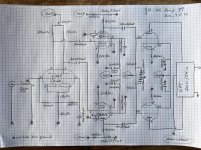
I haven't seen your only now. I have drawn a couple of schematics, your Input not yet included.
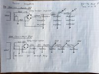
Schematic for one mono amp, one schematic for the GU-46 anode voltage PSU, one for the rest of the tubes, and one for the negative bias supply.
You are proposing to use a hybrid rectifier composed of the above mentioned Schottkys and two pairs of 6CJ3s for one chanel. I wrote this down in my notes.
Greetings, Thomas
I haven't seen your only now. I have drawn a couple of schematics, your Input not yet included.
Schematic for one mono amp, one schematic for the GU-46 anode voltage PSU, one for the rest of the tubes, and one for the negative bias supply.
You are proposing to use a hybrid rectifier composed of the above mentioned Schottkys and two pairs of 6CJ3s for one chanel. I wrote this down in my notes.
Greetings, Thomas
Attachments
Hi Thomas
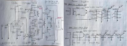
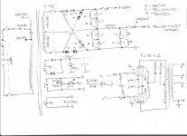
Here`s one very good way to obtain B+1,2KV and Ug2+0,6KV for OPS , that 0,6KV line can be used to supply input and driver stages to, HV secondary is just 2x450VAC , S-By switch need to be one very rugged HV type ,same as B+ HV fuseholder and fuse ,
have no experience with GU46 power pentode but it look as one very interesting tube to me ,
personally I will try with simple three stage amplifier based on slightly modified Mullard 5-20 topology , maybe one 6J5 on input stage DC coupled on two EL84 as phase inverter/driver stage ,and further AC coupled on AB1 class biased GU46 PP-OPS ,
any way many very precision calculations is need to be done before you start making this very interesting and powerful amp.
Regards
Attachments
Thomas,
Mona drew a full wave center tapped B+ setup. Nothing wrong with that, but 1600 V. end to end is exponentially more dangerous than 800 V. That's why I suggested a hybrid bridge. The Schottkys form the connection to ground and the damper diodes form the "hot" connection. The B- supply in "El Cheapo" is a hybrid bridge. You would invert all the polarities, for a B+ supply.
As far as vacuum rectifiers go, forward drop in damper diodes is low. Damper diodes are extremely slow starting, which allows the signal tubes to get fully warm.
Attachments
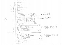
Some time ago, Pete Millett publicized a method for obtaining 2 full wave rectified rails from a single CT winding. Only 5 diodes are needed. By using a combination of choke and cap. I/P filters, it is possible to produce rails that are other than n V. and n/2 V.
Attachments
Dear all,
I am adapting my PSU Idea to the proposal of Banat.
This schematic seems to be relatively simple, and since the trannies will need to be custom wound anyways, it will make sence to combine these in one single large tranny per monoblock.
I will also go for AC heated GU-46, as proposed by Banat.
Does anybody have any comments in the amp schematic itself? Banat proposed using Mullard 5-20 topology, from other sources I have the Info that the GUs should be loaded with low impedance. There was once a thread in this forum of a guy using pmillets schematic with 12gh7 as first stage, but in a SE topology.
Greetings, Thomas
Where can you find that information? It seems the HV capability of the tube is wasted by running it at just 1kV.from other sources I have the Info that the GUs should be loaded with low impedance.
It is BIG...") I like it...
I like it...
Let me suggest something in terms of topology. You'll need EL34 for signal tubes, and a single B+ supply for the plates and front end. Your OPT will need U-L taps( which you can use or not for the GU46's ).
The 500W plate will allow ~200 mA idle current, which working through a 10k a-a load in Class A gives you ability to swing nearly 1kV( a 200 mA idle plus 200 mA more on an increasing g1 swing will take the plate near zero V)
should be able to get 200+ W in Class A. Tasty.
Check out the pdf in post No. 4. Substitute EL34 for the 6AU6...
Looking to build a 25-30 WPC Push Pull amp - Need Help
Also, given the curves, you should set g2 V to deliver 450 mA at g1=0V if you're going to run pentode mode.
Or you could avoid the nutty B+, and run U-L on a significantly lower B+ with less a-a loading. Some calculation is required, and you'll need to get some current measurement at lower than 500V g2 voltage to pick U-L tap location, and a-a loading. And still get some nutty big power.
On the nutty power, you will discover the limits to OPT construction at this size if you manage to continue. going over 200W for the first build is a reasonable target, and sails well into the part of the map labeled, "Here Be Monsters".
cheers,
Douglas
I like it...Let me suggest something in terms of topology. You'll need EL34 for signal tubes, and a single B+ supply for the plates and front end. Your OPT will need U-L taps( which you can use or not for the GU46's ).
The 500W plate will allow ~200 mA idle current, which working through a 10k a-a load in Class A gives you ability to swing nearly 1kV( a 200 mA idle plus 200 mA more on an increasing g1 swing will take the plate near zero V)
should be able to get 200+ W in Class A. Tasty.
Check out the pdf in post No. 4. Substitute EL34 for the 6AU6...
Looking to build a 25-30 WPC Push Pull amp - Need Help
Also, given the curves, you should set g2 V to deliver 450 mA at g1=0V if you're going to run pentode mode.
Or you could avoid the nutty B+, and run U-L on a significantly lower B+ with less a-a loading. Some calculation is required, and you'll need to get some current measurement at lower than 500V g2 voltage to pick U-L tap location, and a-a loading. And still get some nutty big power.
On the nutty power, you will discover the limits to OPT construction at this size if you manage to continue. going over 200W for the first build is a reasonable target, and sails well into the part of the map labeled, "Here Be Monsters".
cheers,
Douglas
Last edited:
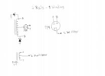
Here`s updated PSU schematic , each GU46 tube can have separate filament winding , separate balancing hum pot and separate analog instrument to monitor IQ for each power tube, I think that each analog instrument need to be calibrated to show around 0,7A at full scale .
Attachments
Each GU46 should have its own filament trans. I like to keep the filament supply separate. Also, a small variac to dial in exactly the right voltage on TT DH tubes is useful. If you grab a filament TX that requires a 10% reduction in primary voltage so that the output is right on, cuts flux density in the filament Iron and leaves it less likely that it will vibrate due to the load.
cheers,
Douglas
cheers,
Douglas
Hi Douglas
I understand your arguments but personally I like compact one single power transformer solution , IMO what is important is to have several taps on the primary side ,it is not bad to have from 230VAC up to 250VAC in 5VAC steps , by connecting main voltage on the right tap will allow to get close as possible that critical 8,3VAC for filament supply .
Regards
Where can you find that information? It seems the HV capability of the tube is wasted by running it at just 1kV.
How much power is the OPT going to be able to handle gracefully? There are a large number of tubes that can make big power from HV, and that HV insulation makes things more difficult. In the scheme of things, IMO of course, even getting north of 100W full bandwidth gets difficult...let alone doing that at HV.
Those anodes will support a substantial Class A amp...likely bigger than good OPT's can be had. The tube has gm in large numbers. Low ratio OPT will help too. Going after a 1 kW, AB design could be done, but I would solve the smaller problems first.
The anodes, judging by its envelope shape are Tantalum, and function as getter and so must be run at adequate dissipation to get them hot enough for that duty.
cheers,
Douglas
So is 200W (1k x 0.2) bias, which is just 40% of Pa_max, hot enough for the anode dissipation?
That was based on an estimate, from a data sheet that I believe listed 'output power' instead of anode dissipation.
For this pup, the maximum continuous anode current may put a lower limit on B+ required to achieve adequate dissipation.
cheers,
Douglas
Dear all
There has already been a GU-46 project on diyaudio, as a SE relatively low power amp.
High power GU46 SE amplifier - help with certain issues
ClassZ seems to have achieved functionality with 12hg7 tubes as direct driver tubes.
This seems to be a working cirquit, at least in SE, with low output power.
This cirquit used after an LTP in pp could be a starting point, this was my assumption.
I do not need 200+ Watt as output power, especially not, when they come to the price of poor sound quality. Therefore the potential costs of this project would be too high.
I like this big tube, and I would like to build an amp that delivers good sound quality. This has higher priority than max output power.
I tend to go with a 200W OPT since this should be enough for pp based on ClassZs Project, run under the same conditions - hopefully.
And Bandersnatch pointed it out - OPTs with ≥200W are getting poorer results than smaller ones, this would support my idea.
Building the real beast could probably be done with this tube, it has hughe potential for high output wattage, at horrifying voltages - this I will leave to the professionals. I have to little girls that need a dad for some more years .
I read a lot about driver tubes now, but I do not have the detailed knowledge to decide what would be the best solution.
Did anybody build something compareable, using maybe EIMACs or other large and powerfull transmitter tubes, run at lets say, relatively low voltages compared to their max specs?
I thought that there have been some PA or stage amplifiers in the 70ties with EIMAC tubes or so... Could be another starting point.
Greetings, Thomas
Last edited:
The biggest so far has been 4E27 run at 600V for ~50W output. 10k a-a OPT( a modified clone of the S-265-Q ). Am next going PP HY51A around the same voltage, with cathode drive to zero bias on the HY51A. This requires some power to drive the IT that will feed the cathodes...
The 4E27 runs a circuit like the 6AU6 St.70; two stages, volt amp/phase split and the finals. The HY51A will be three; two for the driver amp and then the finals.
I like ability to deliver power, but in ~50W increments I use active cross over and efficient speakers...SPL is adequate under most conditions...
Low power with Tantalum anode tubes is problematic; the plates have to come up to operating temperature...and the cathodes have max continuous current limits. At the dissipations required some serious power is available. With the big ones, this power output easily outstrips the OPT's capability to deliver the goods compared to one of say 60-70W( full bandwidth, yes? ).
cheers,
Douglas
- Home
- Amplifiers
- Tubes / Valves
- GU-46 push-pull & single-ended amplifiers