Given the relatively low swing requirement, Thomas’ original design with 12BH7 as the driver could probably handle it without much difficulty. The Philips designs were optimized for maximum output power, which he doesn’t want anyway - so “low power”, zero NFB, Class A might be the way to go.
Actually 'zero NFB' to me means pentode operation, i.e., without the internal triode feedback. But now that you brought it up, what do you think about running the GU-46 in triode, which should lower the output resistance and improve the damping factor, as well as dropping the output power further.
I am just thinking...
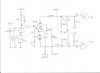
Would it be possible to use the following set up to drive the GUs
1st stage:
6SQ7 (B 350V, Ra 138k, Rc 2k7, Cc 30uF) or 6SJ7 (B 450V, Ra 122k, Rc 2k3, C g2 220nF, Cc 100uF) latter would have lower impedance
2nd stage
6SN7 LTP (B 450V, Ra approx 32k per side, Rc tot 26.5k (made of Rc 1.5k and R rest 15k), R grid 1 and grid 2 to Rc end 1M each, Cc 100nF)
3rd stage
El 84 or EL34 pentode mode or cathode/grid 2 coupled to GU as in the Philips cirquit
Stages connected with coupling caps, eventually using grid stoppers 1k
There are many interesting Feedbacks... This doesnt make it easier.
150W would be fine, but it should come clear and clean. Probably not realistic...
Thomas
Going GU46 in triode mode to me automatically means DC coupled driver stage , going in pentode mode it can be AC coupled also , what important to consider is next , if we have reasonable efficient amp with PP-OPS working in pentode A1/AB1 class mode and is GNFB free, with 1,2 KV-Uba ,Ubg2- 0,6KV and g1/g1` is biased around -65 V than front end/driver stage must deliver around 130Vpp undistorted drive AF signal for full excitation of OPS , good praxis is to design front end/driver stage which can deliver at least twice of that value , that mean around 260Vpp , I think of one topology which can do that is one 6J5 triode on the same input further DC coupled to two EL84 connected as differential pair (phase inverter/driver) working in pentode mode .
Attachments
EL34 with an 10k, resistive plate load, connected up to a 15% 'screen tap', with 50 mA of idle current per tube. A means of delivering a g2 voltage with a 100 mA, g1=0V plate curve will match to this loading. It will be able to do +/- 200V standing on its head, with one hand tied behind its back since it will be looking at the 1kV of B+ that is feeding the finals. Take EL84's as an LTP input stage to drive the EL43's. Try triodes, and if the gain is too high, swap in EL86's whose triode gain is half that of the EL84. If you do pentodes, just cut the driver plate loads.
There is NO need for AB class...or for requiring nuttier insulation that a higher B+ would need. A 500 mA, 1kV supply is no laughing matter, and it will need to be pretty smooth. Rectify with some || 6CJ3's.
cheers,
Douglas
There is NO need for AB class...or for requiring nuttier insulation that a higher B+ would need. A 500 mA, 1kV supply is no laughing matter, and it will need to be pretty smooth. Rectify with some || 6CJ3's.
cheers,
Douglas
These 6CJ3 seem to be difficult to get in larger amounts (I will need 4 per monoblock), and there are no sockets available on eBay... I will have to concentrate in the diode rectifiers, as proposed by Banat.
Or, try a pair of 866's. They sound better than they have any business doing, and they do not live up to their rep for being noisy; I have used their smaller cousins I a few linestage builds...
")
Wishing to correct a previous mistake; sum of current for the proposed EL34 E-linear stage with the finals is 900 mA( not 500 mA; I only counted one final at 400 mA idle), add in the first stage, and you might as well design for 1A...but that is not going to vary with a Class A design...LOL
A full bridge of 2 or three UF5408's in series( 8-12 diodes total ) on something like 1200V rms will deliver 1kV with an LC filter. 3-4 Hy and a large pile of uF will do the trick...
all for less than the likely cost of a single rectifier socket.cheers,
Douglas
Last edited:
BY228G could be used, 1k8Vpeak and 3A.
To drive those tubes, 120Vpp is enough.
Mona
Not enough idle dissipation to heat up the anodes and let them do their getter function. The proposed 1kV/400 mA runs them up to 80% which will get them hot enough.
cheers,
Douglas
Hi Mona
This looks promissing...
Thanks for the analyzes.
My first attempt was probably a bit to weak (directly going on the 6SN7 phase splitter and then to a 12gh7 per phase), but with an additional first stage it could be worth a try...
I know... I am stubborn, but I like these russian 6SQ7 equivalents, they sound very good in combination with 6SN7 LPT. Maybe with a 12gh7 or a 12bh7 or a 6SJ7 as follower...
These 3 stages could deliver the required drive I think.
Especially since all these tubes are here in a box, waiting for their chance.
Thomas
Thanks Bandersnatch for the rectifier clarification. Yes, these large mercury rectifiers... Lovely. I checked them out too... but it would need 2 to 3 of them in parallel per block, meaning additional 15A for the heating. Maybe for a later Project, the weight of this amp will be quite unique without additional rectifier heater iron, I assume.
My last Project made approx. 40kg of Iron and another 45kg for the chassis on rollers...
This time, both amplifier sections shall be in one chassis too. But I believe the Iron itself will be way over 40kg.
My last Project made approx. 40kg of Iron and another 45kg for the chassis on rollers...
This time, both amplifier sections shall be in one chassis too. But I believe the Iron itself will be way over 40kg.
Last edited:
Good sound costs mass, that is sure. My 4E27 amps were comparable, and deliver ~50W. Nothing like grabbing the grid, and making it do as you wish, like a Bernese Mt. Dog, shaking a squirrel...
On paralleling rectifier diodes, hard vacuum are fine, as are SiC Schottky...PN junction and Hg vapour, not w/o balancing resistance.
I see you are next door to Vaud, my father's home...
cheers,
Douglas
On paralleling rectifier diodes, hard vacuum are fine, as are SiC Schottky...PN junction and Hg vapour, not w/o balancing resistance.
I see you are next door to Vaud, my father's home...
cheers,
Douglas
Last edited:
Bandersnatch
How did you run the 4E27's Pentode or triode.
I used Pentode AB2 with Cathode coupling and a little feedback.
Phil
How did you run the 4E27's Pentode or triode.
I used Pentode AB2 with Cathode coupling and a little feedback.
Phil
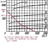
On that load line, for what ever its g2 voltage is( 5 or 600V IIRC ), it should be reduced so the g1=0V line happens at that current delivery. I don't quite see this GU46 running U-L. Local FB pentode will deliver the required output impedance...which is a fine quantity to reduce...
cheers,
Douglas
cheers,
Douglas
Yes, they're equivalents to these DCG4/1000 G in the Philips schematic that jazbo8 has been showing to us.Or, try a pair of 866's. They sound better than they have any business doing, and they do not live up to their rep for being noisy; I have used their smaller cousins I a few linestage builds...
No. As others and I have said, paralleling gas filled rectifiers won't work, at least not without giving up their greatest advantage, their relatively low voltage drop. You'd better go with bigger ones, such as 872's.Yes, these large mercury rectifiers... Lovely. I checked them out too... but it would need 2 to 3 of them in parallel per block, meaning additional 15A for the heating.
Best regards!
- Home
- Amplifiers
- Tubes / Valves
- GU-46 push-pull & single-ended amplifiers