Ok, I will update the schematic. As for the choke, are we talking about the “self BF’ (100R) in the French schematic post #7?
Jazbo,
please correct input grid go to 100K log center pot only
RK 390ohm
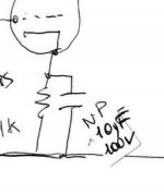
but the self from -57V to grd its correct, itl like this ,
600H 10mA choke cost 60 euro , its here to improve sound ans stability
electrons inside 6C4C hare very happy like this
if 6A3summer give my better combination of capacitor value,OK,
but still this choke go from -57V5 to GRD .
i can put low value resistor in serie to limit current to 10mA,
lower the capacitor 47uF//, we see this lather on

well i have to thanks Jazbo and 6A3summer
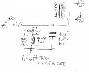
the capacitor // bias choke replaced by 10uF100VNP , it was 47uF.
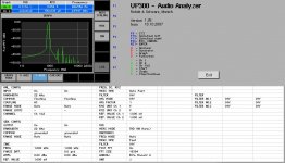
so now the quasi inexistent noise its completely silent,
from -80db to -90db,
so i guess this its improvement.
again thanks.
attached modification and measure
the capacitor // bias choke replaced by 10uF100VNP , it was 47uF.
so now the quasi inexistent noise its completely silent,
from -80db to -90db,
so i guess this its improvement.
again thanks.
attached modification and measure
Attachments
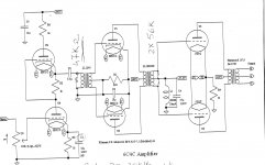
yes its for guitar, speaker celestion vintage30 and 12AX7 china 220K Ra and 2K2 cathode, 100K+100nF to volume pot and go **** rock and rollC3 10uF, R1 390 Ohm, the ones that are circled (2nd stage).
The capacitance is a little too low.
Xc = 390 Ohm at 40.8 Hz, too high of a frequency for a hi fi, maybe ok for a guitar amp.
many others guitar amps :100 Amplifiers, part 2 , 1945 – 54 | Lilienthal Engineering
Last edited:
")
6A3summer,
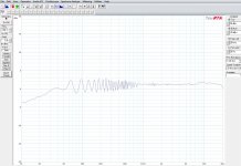
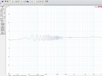
right low end can by linear but its not the cathode capacitor on differential stage to improve, the amplifier its open on my bench, no cap, or cap 10uF or 100uF the difference its only gain , and 10uF its perfect for the sound.
if you want boom boom a 20Hz should improve the cap on first SRPP stage,
i just do and lineariti improve from 20Hz.
sweep by 100uF ans 10uF attached
Attachments

I am still trying to understand the circuit of L1, R10, C4, and R9.
I would think a circuit of bias rectifier, and low pass filter consisting of capacitor, choke, capacitor, and resistor to ground (or potentiometer to ground to make the bias voltage adjustable) would be enough to give bias to the grids through the secondary center tap, and to return the grid bias supply to ground.
I would think a circuit of bias rectifier, and low pass filter consisting of capacitor, choke, capacitor, and resistor to ground (or potentiometer to ground to make the bias voltage adjustable) would be enough to give bias to the grids through the secondary center tap, and to return the grid bias supply to ground.
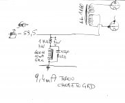
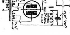
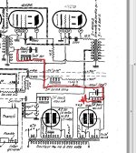
you see in "post 7" attached schematics rectifier go to choke "parallel" to grd not trought "serie"
zoom attached
my choke its afther rectifier and filter its here for improve 6C4C stability and performances
like grid choke
this avoid grid current and improve stability and sound
this its wath i tink but i've not the teoretical knowlege to prove it
thats way i usually do not post schematics, i do becose somebody ask for.
like many poor people think
Master Sakuma San its ignorant nonsense amp builder
i do amplifier like artist make music and i have little teoretical knowlege.
you see i do not pretend to teach nothing i just like nice tube amps
Attachments
Last edited:
claudiomas,
On post #33 you zoomed in to show the bias supply rectifier and the bias supply filter choke.
On the schematic on post #7, look at the Other choke: “self BF 100 Ohm choke” and the 20uf capacitor that connects to the secondaries of the interstage transformer which drives the two 4Y25 tube control grids.
You will notice that one end of the self BF 100 Ohm choke connects to the negative bias supply, and the other end connects to the junction of the two interstage secondaries plus the top of the 20uF cap. The 'bottom' end of the 20uf cap connects to ground. Neither end of the self BF 100 Ohm choke is connected to ground in post #7.
Your schematics show the choke and cap both going to ground at the interstage secondaries (including the schematics that have a 1k Ohm resistor in series with the choke). Those are not connected the same as the schematic in post #7.
Last edited:
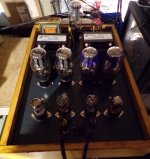
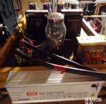
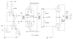
i made a new amplifier lower cost for myself
6SN7 ans 6C4C , hammond transformers, cathode bias.
splitter driven by 6SN7 SRPP its hammond 560Q 40K/20+20K
driver its hammond 124F https://www.hammfg.com/files/parts/pdf/124F.pdf
output 1650H
smps HT power supply 420V350mA 5U3C choke oil cap
7.5V smps heathers
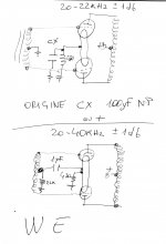
this morning i'm tryng WE trick , no cathode cap usually high value, i use 100uF NP
but 1uF MKP with driver IT secondary to ground by 22Kohm
linearity from 20/20K +-1db grow to 20/40KHz +-1db
like this
http://lilienthalengineering.com/wp-content/uploads/Western-Electric-42-Amplifier-original-schematic.png
6SN7 ans 6C4C , hammond transformers, cathode bias.
splitter driven by 6SN7 SRPP its hammond 560Q 40K/20+20K
driver its hammond 124F https://www.hammfg.com/files/parts/pdf/124F.pdf
output 1650H
smps HT power supply 420V350mA 5U3C choke oil cap
7.5V smps heathers
this morning i'm tryng WE trick , no cathode cap usually high value, i use 100uF NP
but 1uF MKP with driver IT secondary to ground by 22Kohm
linearity from 20/20K +-1db grow to 20/40KHz +-1db
like this
http://lilienthalengineering.com/wp-content/uploads/Western-Electric-42-Amplifier-original-schematic.png
Attachments
Last edited:
preliminary schematics
The first gain stage is not SRPP, but a half-Mu gain stage.
- Status
- This old topic is closed. If you want to reopen this topic, contact a moderator using the "Report Post" button.
- Home
- Amplifiers
- Tubes / Valves
- 6C4C E80CC PP IT coupled