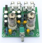
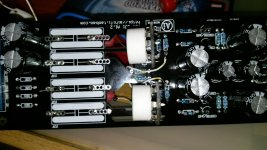
There is a plethora of 6J1 valve pre-amps on ebay from china/hong kong.
Photo of a typical example is below.
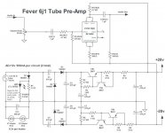
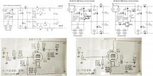
I would like somebody to confirm the circuit diagram is the correct one. I've buzzed 3 resistors (not the ones in the voltage multiplier) and they match so I am reasonably sure it is correct.
But I would like to know how to convert the circuit to unity gain (i.e. to behave as a buffer). The potentiometer is to be removed and resistors to control the gain changed - but so that there is not clipping and frequency response is unchanged - hopefully that is possible.
My guess gain is set by (R13 / R14) = 470 k / 200 or by comparing to another circuit I have, is it (R16 / R150 = 100 k / 4.7 k ?
Photo of a typical example is below.
I would like somebody to confirm the circuit diagram is the correct one. I've buzzed 3 resistors (not the ones in the voltage multiplier) and they match so I am reasonably sure it is correct.
But I would like to know how to convert the circuit to unity gain (i.e. to behave as a buffer). The potentiometer is to be removed and resistors to control the gain changed - but so that there is not clipping and frequency response is unchanged - hopefully that is possible.
My guess gain is set by (R13 / R14) = 470 k / 200 or by comparing to another circuit I have, is it (R16 / R150 = 100 k / 4.7 k ?
Attachments
As no NFB loop is present, the gain (α) of a triode is controlled by the amplification factor (μ), the plate resistance (RP), and the net load. A complication is the unbypassed cathode bias resistor. The absence of a bypass cap. introduces degeneration, AKA local current NFB, which raises the effective RP.
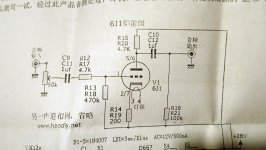
The 6J1 data sheet is (at least to me) confusing. The type is a pentode, but the plate curves shown are for triode wiring. Somebody with Hanji skills might offer a better insight.
The schematic provided shows, in an unclear manner, the tube being triode wired. Pin 6 is the screen grid (g2), but it's shown as a plate connection.
gain of unloaded grounded cathode triode is:
A=(mu*Rp)/((rp+Rp+(mu+1)*Rk)
where mu and rp are properties of the tube, Rp is the external plate R, Rk the cathode R.
6j1 is a pentode which is triode connected in this case;
Chinese datasheet does not give numbers for trioded mu and rp but curves for triode connection;
from these a rough estimate gives mu of 30 and rp of 5kohm.
So gain is approx. 24, unloaded. Gain is lower when loaded.
Now there is already a load of 100kohm which has to be calculated as parallel to Rp.
This reduces gain to 22.
If we assume that whatever is driven by this pre has input R of again 100kohm, we end up with something like 20.
This preamp is explained here:
Tube preamp kit FE-6J1-2.0B |
Note: R16/R21 must be cnnected to ground.
Tube preamp kit FE-6J1-2.0B |
Note: R16/R21 must be cnnected to ground.
The 5654 pentode was designed for good VHF/UHF gain: low grid input conductance and hence low grid noise were the aim. It is not particularly linear, so I don't understand why it is so popular for audio. Anyway, to turn this circuit into a buffer you need to rejig it as a cathode follower.
I would add that a properly functioning buffer is transparent, most definitely not an effects machine.
High transconductance (gm) leads to low O/P impedance in a cathode follower. Combine high gm with reasonably high plate current (IB) and you have something that can drive some pretty miserable loads. The 5687/6H30Π (6n30p)/ECC99 group of "super triodes" fill the need well.
High transconductance (gm) leads to low O/P impedance in a cathode follower. Combine high gm with reasonably high plate current (IB) and you have something that can drive some pretty miserable loads. The 5687/6H30Π (6n30p)/ECC99 group of "super triodes" fill the need well.
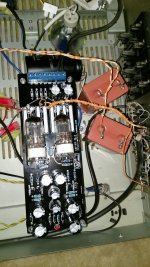
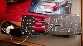
I have bought exactly this circuit and it sounds disapointing. High output impedance and a lot of distortion if driven harder. So, before simply throwing it to a trashbin, I wanted to try to convert it to a buffer. I am not ready to waste a lot of time on it, so a couple of quick modifications will do, but no more. I already replaced those yellow input/output caps with better ones. Also, I reconnected a 470k resistor as it was not referencing the grid to ground, but to -24v supply (it is powered with +-24v supply via voltage doubler from 12v ac).
So, I guess tha I have to bypass that 4.7 k anode resistor (connect anode directly to +24v supply) but then I am wondering about the value of cathode resistor (200 ohms) on that schematic? What should be its new value?
Of course, output will be taken from the cathode...
So, I guess tha I have to bypass that 4.7 k anode resistor (connect anode directly to +24v supply) but then I am wondering about the value of cathode resistor (200 ohms) on that schematic? What should be its new value?
Of course, output will be taken from the cathode...
Attachments
No point in using "better" caps in a poor circuit. The existing circuit is correct in referencing the grid to -24/28V, but the cathode follower version should not.
As I said, the 4.7k anode resistor should be put in the cathode circuit. The 200 ohm resistor stays, as that provides bias.
As I said, the 4.7k anode resistor should be put in the cathode circuit. The 200 ohm resistor stays, as that provides bias.
If you do that the current in the tube becomes very low, not good.It is the 100k at the output that need the change.Also, I reconnected a 470k resistor as it was not referencing the grid to ground, but to -24v supply .
The power supply treats the transformer very badly, single phase rectifier for the heaters

Here are the originals with 100k mod and two alternative supplys.
Also a very simple buffer mod
Mona
Attachments
Can schottky diodes be used in the voltage multiplier circuit (d2-d5) instead of the 1n4007?
As long as their PIV rating and current capacity is adequate.
cheers,
Douglas
Yes. More current, which may or may not improve results a little.02GF74 said:Could r15/20 (4.7k) be used for r14/19 (10k). What would be the effect of using the lower value resistor?
- Home
- Amplifiers
- Tubes / Valves
- ebay 6J1 valve pre-amp - circuit diagram/gain