As long as their PIV rating and current capacity is adequate.
cheers,
Douglas
With 12v ac supply I understand that the capacitors and diodes won't see more than 12v rms.
So to reduce the vf across the diodes, a 1n5817 should be fine.
Spec below.
Code:
              1N5817  1N58185  1N5819
Vr peak   	20       30   	   40
Vrms      	14   	  21   	   28

Vf @ 0.1A      0.2       0.3      0.6
Vf @ 0.2A 0.25 0.35 0.75Take it that it will not be OK.
There are essentially two ways to bias a cathode follower: apply the correct DC voltage to the grid, or use a small value cathode resistor. If you connect the grid resistor to -39V instead of 0V then you are applying the wrong DC voltage to the grid so the valve will conduct almost no current so create significant distortion.
There are essentially two ways to bias a cathode follower: apply the correct DC voltage to the grid, or use a small value cathode resistor. If you connect the grid resistor to -39V instead of 0V then you are applying the wrong DC voltage to the grid so the valve will conduct almost no current so create significant distortion.
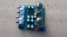
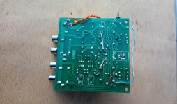
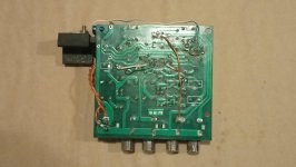
Completed mods and except for one mistake have it working, top and underside of board below.
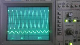
The regulated supply to the heaters has eliminated buzz in L channel (was present with no input and pre-amp volume turned to 11) but when testing I could see on the 'scope there is a fair bit of crosstalk, which can be heard with signal applied to only 1 channel, (pre-amlp volume at 11).
I did same listening test on the original circuit - and there was similar cross talk on R channel.
So I am wondering as to the reason for this. My own opinion of the layout is not great - I would have kept inputs on the opposite side to the outputs.
1. there is pick up as the two input signal tracks run parallel to each other (see underside, lowest 2 horizontal tracks
2. the signal leaks across either through the 0 V rail (R13/18) or via the -ve rail (R14/19)
3. other?
update: even with valves removed and circuit not powered, seeing crosstalk. Resistance between both inputs as shown by dvm is ∞.
suggestions as to where to look?
Attachments
Last edited:
update 1: even with valves removed and circuit not powered, seeing crosstalk. Resistance between both inputs as shown by dvm is ∞.
update 2. as above; at about 100 Hz, I'm seeing the amplitude on the unused input start to rise and reach maximum at about 60 kHz - that to me seems to imply pick-up on the parallel tracks?
I'm wondering whether it is worth cutting the tracks for the inputs and replacing with screened cable?
update 2. as above; at about 100 Hz, I'm seeing the amplitude on the unused input start to rise and reach maximum at about 60 kHz - that to me seems to imply pick-up on the parallel tracks?
I'm wondering whether it is worth cutting the tracks for the inputs and replacing with screened cable?
Last edited:
The power supply treats the transformer very badly, single phase rectifier for the heaters
Just to confirm this. The transformer got very warm in original circuit, just about too hot to touch. Having a rectifier off the ac with 7812/diode, the transformer is barely warm.
Hi guys,
Thanks for the good advises.
I have a bit different board but very similar, so what I have done =
1.Repalced all the junk caps with better ones, all bypassed by 100 nano.
2.Replaced the cathode res with normal metal film 212 R bypassed by lityc 2.2 uF Vishay BC 128
3.Replaced anode res with 6k8
4.Removed and cut off all supply tracks for the heaters and installed a simple trafo 220 > 12 V AC / some day in a good mood will feed the tubes with separate supply of 6.3 V AC each/
5.Output cap are 4.7 uF good brand.
6.I have all kind of tubes but for the timebeing listening to 6564W.
Please share any ideas, let,s try to make the cheap thing sounds better
Cheers
hi guys,
i'm also building this preamplifier and i'm undecided whether to leave it with 12v and some improvements or if to increase the voltage to 18v, only then i can't understand what value i have to change to the anode and grid resistance so as not to work badly the valve.Thanks in advance
i'm also building this preamplifier and i'm undecided whether to leave it with 12v and some improvements or if to increase the voltage to 18v, only then i can't understand what value i have to change to the anode and grid resistance so as not to work badly the valve.Thanks in advance
- Home
- Amplifiers
- Tubes / Valves
- ebay 6J1 valve pre-amp - circuit diagram/gain