If you are using Solid-state rectifiers, (e.g. SiC), 40 Ω is probably OK. It will also allow you to try larger capacitors, in future: for my 300B-SE, I use 2x 820µF 550V (CRC with 10Ω ), followed by a capacitor-multiplier and film caps 30µF 630V mounted near the OT.
Separate supply for each L & R channel.
This arrangement separates the rectifier recharge pulses from the audio supply-current, which is very helpful for good sound.
Lower voltage on your C1 is certainly good!
Separate supply for each L & R channel.
This arrangement separates the rectifier recharge pulses from the audio supply-current, which is very helpful for good sound.
Lower voltage on your C1 is certainly good!
It is the plan to switch to the Cree SiC diodes instead of the "normal" bridge I use in the moment. The Cree TO-220 comes in may current variations. I have looked at a 15A version. The different variants goes down to at least 2A in the TO-220 housing. Is there a benefit of use one low current rating but sufficient rather than using one which has a rating much higher then needed? .....the price difference is not that huge considered that only 4 is needed.
I Use the 2A Cree, but I have 2 supplies, 1 for L and 1 for R, and this is well worth doing.
The stressful time for the diodes is at startup. The maximum repetitive peak forward current is about 8A for the low power diode, and series-resistance in the rectifier is needed, to control peak current. PSUD2 allows you to find the resistor value - or you can use bigger diodes, mounted on insulated heatsinks.
The stressful time for the diodes is at startup. The maximum repetitive peak forward current is about 8A for the low power diode, and series-resistance in the rectifier is needed, to control peak current. PSUD2 allows you to find the resistor value - or you can use bigger diodes, mounted on insulated heatsinks.
I Use the 2A Cree, but I have 2 supplies, 1 for L and 1 for R, and this is well worth doing.
The stressful time for the diodes is at startup. The maximum repetitive peak forward current is about 8A for the low power diode, and series-resistance in the rectifier is needed, to control peak current. PSUD2 allows you to find the resistor value - or you can use bigger diodes, mounted on insulated heatsinks.
If the B+ with PT etc. was moved to a separate box or board. How does that work in general with wire connection and high voltage connectors etc.?
I watched at the "Bartola" homepage that is seems very long cables (DC) from the PSU to the amp can work. The filament reg. has to be close to the tube of course.....but not necessarily the B+?
It is really the "PSU stuff" that is the most complicated in a tube amp.
Now I finished the external PSU (B+ and Rod Coleman Raw PSU). Next step is to build what is necessary in the amp itself. It will be wire connections and the Rod Coleman filament regulators and mount the cathode resistors without the hum pots.
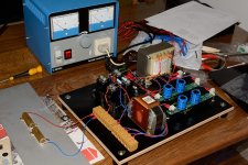
I tested the B+ using 2 x 2k 50W resistors in series as load mounted on an alu. board as with 535 VDC and 130 mA it generates some heat. After re-designing the PSU going from a simple C-R-C filter to a R-C-L-C filter using a Lundahl double choke in "common mode" configuration the B+ was more or less spot on the expected value.
It is difficult to measure the ripple using my Tek2225. I mounted a 0.1 uF capacitor in serie with a 1M resistor to charge the capacitor. I only want to measure the AC and not damage probe and scope with the high DC voltage. But difficult to get a stable trace on the scope. But it seems ripple is about 1 mV or so......as expected. Very small changes in the 230V AC.....less than 0.5 V seems to affect the scope image even in AC input mode. There is probably a way to out-compensate the small AC variations which causes small DC variations less than 1 Hz. The trace jumps up and down.
Do you know what I am talking about?")
The 2225 scope has some possibilities when using both channels. It can invert CH2 and there is also an ADD function. Think there is a technique I need to learn........
I tested the B+ using 2 x 2k 50W resistors in series as load mounted on an alu. board as with 535 VDC and 130 mA it generates some heat. After re-designing the PSU going from a simple C-R-C filter to a R-C-L-C filter using a Lundahl double choke in "common mode" configuration the B+ was more or less spot on the expected value.
It is difficult to measure the ripple using my Tek2225. I mounted a 0.1 uF capacitor in serie with a 1M resistor to charge the capacitor. I only want to measure the AC and not damage probe and scope with the high DC voltage. But difficult to get a stable trace on the scope. But it seems ripple is about 1 mV or so......as expected. Very small changes in the 230V AC.....less than 0.5 V seems to affect the scope image even in AC input mode. There is probably a way to out-compensate the small AC variations which causes small DC variations less than 1 Hz. The trace jumps up and down.
Do you know what I am talking about?
The 2225 scope has some possibilities when using both channels. It can invert CH2 and there is also an ADD function. Think there is a technique I need to learn........
Attachments
I call what you are observing "line bounce" (power line bounce).
Your refrigerator turns on, then the wife's hair hair dryer turns off. Your neighbor's water heater turns on, etc. . . . . You are all on the same power transformer on the pole outside your homes.
If you do not regulate the B+, you will see this.
I just live with it. And the following example may encourage and convince you to live with it too:
Suppose the 300B plate resistance rp is 750 Ohms. And suppose the output transformer primary is 3500 Ohms, and 20 Henrys.
At 1Hz, the inductive reactance is 125 Ohms. That means most of the B+ 0.5V "bounce"
is across 750 Ohms, and the least of the 0.5V is across 125 Ohms inductive reactance.
125/(750 +125) = 0.143. 0.5V (0.143) = 71mV.
But the output transformer voltage step down is is Root(3500/8Ohms) = 21:1.
71mV/21 = 3.4mV at 1 Hz.
What woofer will cause any sound, or cause any distortion of the desired music, if there is also
an undesired signal of 3.4mV at 1 Hz?
The measurement you are doing with the 0.1 uf cap and 1 meg Ohm to measure the ripple has a low frequency roll off of -3dB (70.7 % of the voltage) at only 1.6Hz (very low). That is far below the 60/50Hz and 100/120 Hz ripple you are trying to measure.
Use a .005 uF cap and 1 meg Ohm. That is about -1 dB at 60Hz (about 10% error). If you read 1 mV ripple that would be about 1.1mV.
But the advantage is that very low frequency "line bounce" will be very reduced, if not eliminated from the measurement. It will be easier to see the 50 to 120 Hz ripple (be sure to use the Line trigger source setting on your scope). And measure the ripple 2 ways: with trace averaging; and without trace averaging (if your scope has that).
Happy unworried listening!
Last edited:
Thank you for that answer.
An good idea to use a "smaller" cap for ripple measurement to cut of the low frequency variations. I think most live with small variations in B+ caused by the main voltage.
The ripple I was able to see looked different from what I normally see when there is just a capacitor after the bridge. It was very smooth.....more like a sinus that a sawtooth shape. It must be the choke which causes that.
I don't think the scope has trace averaging.
The scope has an ability to inverse the CH2 and then an Add function to CH1. I was thinking if it was possible to only have the low frequency on CH2 and reverse it and add CH2 to CH1 so it will be a subtraction and then out-compensate the low frequency. The smaller cap sounds like a better solution
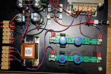
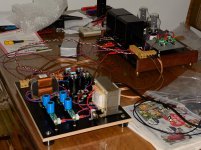
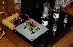
I finished the rebuild of external PSU and modifications to the main amp cabinet. The Coleman regulators was placed on top of the chassis on a 3mm piece of aluminium. Approx. 12 x 12 cm. It seems to be fine as heat sink. It never gets hotter than it is possible to put a finger on the aluminium.
For adjustments I started just by inserting the 300B and voltage was about 3.5 V DC with pot adjusted as low as possible. Then I could adjust it to 5 V very easy. When I inserted the small tubes and after a while turned on the B+ it was necessary to adjust the 300B filament by approx. 0.1 V up.
The voltage on the 300B cathode resistors is now 180 V - 183 V and before it was 177 V - 180 V. I guess this is OK. I use the filament + side for the cathode resistor.
I measured hum with RCA input shortet on the 8 ohm output. I measured 0.0 - 0.1 mV AC so very little. I have a head phone adapted mounted and it is 100% silent when I insert a head phone. Before the modifications the hum was very audible.
So far so good.....next step it to hear some music on it. I am confident that it will be fine.
Attachments
There was a lot of considerations when the process was ongoing
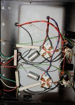
The question is now what the main cause was for the 3-4 mV AC hum on the output. 120mV Ripple on B+, 55 mV ripple on 5V or was it that the PSU trafo was too close to the OTs and 300B tubes? .....maybe a bit of each.
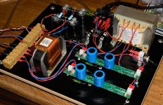
The look of the underside of the amp is now much cleaner.......
The question is now what the main cause was for the 3-4 mV AC hum on the output. 120mV Ripple on B+, 55 mV ripple on 5V or was it that the PSU trafo was too close to the OTs and 300B tubes? .....maybe a bit of each.
The look of the underside of the amp is now much cleaner.......
Attachments
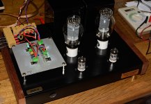
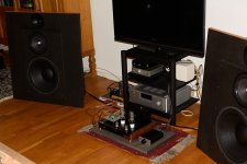
Now I tested the amp on my speakers. It is 100% silent (94 dB speakers). No hum/noise even if I put my ear as close as possible to the speakers.
They also plays amazing. Very clear and transparent high/middle and really good bas. This is with Electro Harmonix 300B and Tung-Sol ECC83. So there are possible upgrades for the future.
So a DHT SE triode amp can be 100% hum free....I was a bit in doubt in the begining......
I stream 16 or 24 bit music and use a passive preamp (24 step attenuator) to have the signal path as short as possible.
Attachments
- Status
- This old topic is closed. If you want to reopen this topic, contact a moderator using the "Report Post" button.
- Home
- Amplifiers
- Tubes / Valves
- 300B SET amp measurements without tubes installed