It's a better circuit than just setting up the driver's anode voltage. The resistor network also allows the driver triode ECC83 to help stabilise the 300B anode current. (If the 300B draws more current, the ECC83 anode voltage increases, and the driver then increases current, lowering the 300B current).
This dc-stable configuration of driver and 300B output has a big advantage: it allows dc-coupling between driver and 300B grid. Many power-triode designs use capacitor-coupling to the grid, which easily leads to the capacitor acquiring dc-voltage during large-signals. (web search "grid blocking distortion", for more).
DC-coupling solves the blocking distortion problem more simply than adding a power-FET grid driver, and reduces the risk of grossly overdriving an expensive 300B. But, at the cost of the very high anode voltage supply.
On paper it looks by a very simple design and it seems also a clever design after reading your response. Despite the hum the sound is very good. I therefor hope that I am able to reduce the hum to below 1 mV.
Now I tested after re-wire with tube inserted. Still hum as expected. A lot more in left speaker than right speaker. The PT is closest to the left OT and the 2 x 7805 DC regulator board. When heater voltage is turned on (no B+) then it is mostly hum in the woofer. When B+ is on then a bit more hum in the woofer and then also some 100 Hz in the middle and a small amount of buzz in the tweeter.
When B+ is turned on the amplification is turned on also I guess so it could still be the 55 mV ripple on the 5V DC rather then ripple on B+?
When B+ is turned on the amplification is turned on also I guess so it could still be the 55 mV ripple on the 5V DC rather then ripple on B+?
If the PT is too close to the Left OT, can you remove the chassis-screws to the OT, and try rotate and/or move the OT? Please be sure that the OT is still grounded when you try this test - for safety and hum performance.
If you like the sound of the amp, you will need a much better solution for heating the 300B. A 7805 is bad enough for the sound, and the small filter caps in the raw DC make it noisy and worse-sounding. Also, you will need a separate transformer for the heating supply: using a winding in the B+ PT will cause the Ampère-level rectifier current-pulses for the heating-supply to be coupled into the B+ supply. A C-R-C or C-L-C supply is usually not enough to filter these out.
BTW what rectifier diodes in the heating supply? If these are not schottky diodes, or suitable fast-recovery diodes -- the buzz will be worse, and the sound will suffer, because of the broadband current-peaks as the diodes turn-OFF.
If the PT is too close to the Left OT, can you remove the chassis-screws to the OT, and try rotate and/or move the OT? Please be sure that the OT is still grounded when you try this test - for safety and hum performance.
If you like the sound of the amp, you will need a much better solution for heating the 300B. A 7805 is bad enough for the sound, and the small filter caps in the raw DC make it noisy and worse-sounding. Also, you will need a separate transformer for the heating supply: using a winding in the B+ PT will cause the Ampère-level rectifier current-pulses for the heating-supply to be coupled into the B+ supply. A C-R-C or C-L-C supply is usually not enough to filter these out.
BTW what rectifier diodes in the heating supply? If these are not schottky diodes, or suitable fast-recovery diodes -- the buzz will be worse, and the sound will suffer, because of the broadband current-peaks as the diodes turn-OFF.
As you can see from the picture there is not much space for moving around with the tranformers and the wires are not long enough.
No schottky diodes are used. The Pete Millett DC supplies which is on the way uses schottky diodes. The B+ also uses a normal rectifier bridge rated 600V.
Since the hum is much more audible in the left speaker (woofer) one should think that it is because the PT is closer to the left OT than the right OT. How does it look at the picture? .....too close?
The PT is rated as follows:
1 x 416V (300 mA) for B+
1 x 6.3V (1.5 A) for ECC83 heaters
2 x 7.6V (2.5 A) for 300B filaments
The OT's are from Welter in Germany and the PT is a Danish brand. Quite good komponents are used in the amp so could be fun to have it "silent".
I am close to take the decision to move the PT to another cabinet and then also find a transformer for the 5V DC. I wonder if 6.3V would be the best choice for the Pete Millett filament regulator for make 5V.
There will be a challenge to fint a connector between the two cabinets for the 416V AC. I wonder if banana plugs can be used? .....a normal 250V connector will probably work also.
As hum/noise level is quite low at the right speaker it seems that the B+ filtering may be ok and my main problem is the 50 Hz from the PT and then some buzz from the current 7805 DC regulators?
Attachments
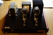
Yes, the PT is too close to the OT and too close to the 300B. Even the OT is too close to the 300B - big DHTs are good at picking up from stray fields.
Running the anode at 535V through a bridge rated for 600V is too close for my taste, also. And these integrated bridge modules have very slow recovery times, and generate plenty of noise.
For solid state B+ rectification, the Wolfspeed (Cree) 1200V SiC diodes are the real thing.
Running the anode at 535V through a bridge rated for 600V is too close for my taste, also. And these integrated bridge modules have very slow recovery times, and generate plenty of noise.
For solid state B+ rectification, the Wolfspeed (Cree) 1200V SiC diodes are the real thing.
Are the laminations of the PT perfectly square? Hard to tell from the picture. If they are it looks like the feet could be moved to one of the sides and you could try it lying on it's side right where it is????
They could probably be moved a little bit......but I think I have decided to move the PT to its own cabinet.......
Yes, the PT is too close to the OT and too close to the 300B. Even the OT is too close to the 300B - big DHTs are good at picking up from stray fields.
Running the anode at 535V through a bridge rated for 600V is too close for my taste, also. And these integrated bridge modules have very slow recovery times, and generate plenty of noise.
For solid state B+ rectification, the Wolfspeed (Cree) 1200V SiC diodes are the real thing.
Thank you for the information!
I will look at the Wolfspeed (Cree) diodes.
Today I measured B+ = 542 V.
The Jensen capacitors has a rating of 550/595 VDC and I don't know what that really means because the first capacitor in the C-R-C filter is running at 570 VDC.......that is above 550. Let us hope the "Jensen" is good quality. The 595 is probably short term DC (spikes) and 550 the long term......but not sure.
What is a good quality B+ for a 300B tube regarding ripple?
I have simulated my PSU in the PSU designed and my diff voltage at B+ is approx. 128 mV (p-p). Is that bad?
Think I will try to move the PT to another cabinet. I also need the space on the top for the Pete Millett regulator. It is too high to be mounted where the 7805 regulator is mounted.
They could probably be moved a little bit......but I think I have decided to move the PT to its own cabinet.......
Not to move it but on it's side it will rotate it 90 degrees. "Might" fix your problem. Simple solution if it works. That is all.
Thank you for the information!
I will look at the Wolfspeed (Cree) diodes.
Today I measured B+ = 542 V.
The Jensen capacitors has a rating of 550/595 VDC and I don't know what that really means because the first capacitor in the C-R-C filter is running at 570 VDC.......that is above 550. Let us hope the "Jensen" is good quality. The 595 is probably short term DC (spikes) and 550 the long term......but not sure.
What is a good quality B+ for a 300B tube regarding ripple?
I have simulated my PSU in the PSU designed and my diff voltage at B+ is approx. 128 mV (p-p). Is that bad?
550/595V usually means:
1. 550V "Working Voltage" - where the capacitor is providing Ripple-Current (charging/discharging of the cap, to support dc current at the load)
2. 595V Surge Voltage: Where there is (near) Zero load current, and the time is limited to 3 minutes.
So, the continuous voltage should be lower than 550V, and preferably 5-10% lower. The lifetime at 570V will be quite short, and it may begin to get warm if the amp is left on for a while. A hot capacitor is a bad sign.... Be careful in summer time!
Solution: Stack 2x 470µF/400V caps in series, with 220K 3W resistors across each cap., for balancing. Gives an effective 230µF 650V cap.
Over 100mV of ripple on the anode supply is too much for low-noise performance. Time to add the choke!
The power supply now, is not fit for purpose. It needs to be rebuilt on a fresh chassis, with suitably rated capacitors, chokes (or capacitor multiplier circuit). Before building it, check that the ratings of all parts are met, and that the ripple voltage is is the low-mV region, and current delivery matches the amp's needs.
If I exchange the 220R filter resistor in the PSU for B+ to a 10H (130R) choke the ripple drops from 128 mV (pp) to below 5 mV (pp) in the simulation. The B+ raises to 552 V or so. It may be ok or it could be reduced by added a low value filter resistor?
I take it step by step. 1. priority is to reduce the hum in left channel. As both channel gets the same B+ it is probably the PT to close to the left OT that is the main problem. I will try to do "something" that can prove that this is the case........
In this amp I may keep the capacitors. I trust Jensen Audio grade capacitors is high quality......
I will ask for a data sheet.
About the distance from PT to OT I watched this on the web.
I discovered that all the bords in the front seems to be the PSUs for the amp in the baggrund. Compared to this I agree that my distance is at the "short side"!
A nice idea to build an amp on a piece of "furniture wood".
I discovered that all the bords in the front seems to be the PSUs for the amp in the baggrund. Compared to this I agree that my distance is at the "short side"!
A nice idea to build an amp on a piece of "furniture wood".
Attachments
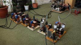
This was a first test of the full madness before racking them on the shelves. I mostly all times separate PSU from my amps. Mainly for flexibility to swap out sections and reuse PSUs but also to ensure I make it dead quiet
So it is your PSU's and Amp's!
It looks really impressive!
I don't think I will ever reach that level in DIY tube amps.
Even as DIY is looks quite expensive. But good that we can get some advices when we run into problems.
Think I was searching for the "Rod Coleman" filament regulator and came across your homepage.
You are right that it looks a bit like "madness". You need a "good wife" or "no wife" to have this permanent in the living room
")
It was originally a 4-65a SE Amp in Class A2 which morphed into the 814 in triode mode. All DHT and DC coupled. A fantastic amp and experiment which lasted for a couple of years. I pushed it out to the loft where it resides now when my daughter was born.
Here you have more info: 814 SE A2 Amplifier – Bartola(R) Valves
Today I run a 4P1L PSE amplifier (output stage only) with a varied set of different DHT preamps (01a, 10Y, 4P1L, 2P29L, etc.) to form a 2 stage DHT system.
Before when my daughter wasn't around I could have the luxury to build everything in a wood board to speed up the build process. Now, everything is in a proper case.
I taught her from day one the danger of getting close to the amp cabinet so she never gets even close to it when I'm running the amps.
My wife is forgiving, but she's running out of patience am afraid
Also if you have dogs etc. in the house a wet nose on the anode of a transmitting triode at 2kV will have some interesting results. The pictures with the many PSU's in the living room looks like it could be one of these big triodes (I am not expert in all the numbers). I do know the WE212 which I have never heard......but would like to.
By the way I have changed "horse" and sent a mail to get the Rod Coleman regulators for the 300B instead of the Pete Millett LT1084 based regulator which is on the way and I have all components etc.....I may be able to use it for some other purpose. A small standalone variable power supply maybe......
By the way I have changed "horse" and sent a mail to get the Rod Coleman regulators for the 300B instead of the Pete Millett LT1084 based regulator which is on the way and I have all components etc.....I may be able to use it for some other purpose. A small standalone variable power supply maybe......
I have tried in one channel to unsolder the wire at the ECC83 end but no change in hum level. I did not remove the ground connection on the 0 at the OT. I belive that it is only necessary when NFB is used. It is a very short wire back to the *-ground so I considered this not a problem........but you never know.
I played with the PSU designer to change from a C-R-C to a C-L-C using a 10H/130R choke I have found still using the same PT and 220uF capacitors. The problem here is that the output voltage gets too high. Then I tried to simulate a L-C-R-C filter but then the output voltage was too low (very low) even with a 1 ohm resistor. Then I tried R-C-L-C .....and it worked with R = 40 ohm or so. Another advantage is that the voltage on C1 is lowered which is good.
Any problems with such a design for the B+ PSU?
Any problems with such a design for the B+ PSU?
- Status
- This old topic is closed. If you want to reopen this topic, contact a moderator using the "Report Post" button.
- Home
- Amplifiers
- Tubes / Valves
- 300B SET amp measurements without tubes installed