@Tom: separate filament transformers are a must, as with DHT's the filament (= cathode) is audio.
Do you mean separate filament transformers or separate filament taps? As far as I know the vast majority of amplifiers have a single power transformer with a separate tap for each DHT. IDHT's can generally be heated from a single common tap.
I thought that if you wanted to heat the tubes before applying the HT this can be achieved by in a single power transformer have two switches. One on the primary side and another on de center tap op the HT winding.But, also for the sake of start up, a separate filament transformer is best.
Tom
Hello Johan, I hope I read your message right. I agree that the power transformer is not in the signal path and should not have a impact on the sound quality as such. However there are in my experience (solid state amps) 'qualities' such as quiet operation, minimal stray fields, isolation form mains noise that do have an impact on sound quality. Although not backed up by empirical evidence (never had the opportunity to try) I have a suspicion that running a core a high flux density to improve efficiency also has an impact on sound quality.Not to expand this to a design discussion, but I must respectfully disagree with Schmitt 77 regarding the 'sound' influence of a power transformer. A transformer provides the neccessary voltages; the dc after rectification and filters is determined by everything, and any single source has its own heavy enough bypass capacitor. Unless transformer windings are so thin as to influence regulation, I fail to see how the power supply proper is anything but plainly a dc short at audio frequencies.
Tom
Last edited:
Hallo Tom, groeten vanuit New Zealand.
Here in New Zealand not even winders are easily to be found. Why not buy a Hammond transformer from Mouser? Above 100 USD they'll ship for free and that is cheaper than anything you can wind locally. Make sure to check out the way they calculate the load capability.
Hallo AmadeusMozart, bedankt! Hartelijk groeten uit Haarlem
I checked the Hammond catalogue and they do have a model (302AX) that would suit my needs (correct voltages). Price is 147,- euro and shipping is indeed free for orders over 100,- euro.
With regards to the load capability. The examples they provide are all for solid state diodes, and I plan to use a tube rectifier. Now, I know that a tube rectifier has a significantly larger voltage drop then a SS diode, but does a tube rectifier also impact the current capability?
Tom
Last edited:
@Tom: with respect to separate filament transformers for DHT's, in your reply to Johan you say that the power supply transformer is not in the signal path. Because the filament of a DHT is also the cathode, the "filament" carries the signal. You would not want any coupling there in a power supply transformer, that's why the need for a separate filament transformer.
There are several ways to start up a DHT amplifier, for example like the way you describe. Another option: with separate transformers and two multipole switches you can start up the amplifier by applying filament power first and HV next; switching off HV first, filament power last. Not important which switch first, always the right procedure (a schematic of this can be found in Sound Practices magazine).
There are several ways to start up a DHT amplifier, for example like the way you describe. Another option: with separate transformers and two multipole switches you can start up the amplifier by applying filament power first and HV next; switching off HV first, filament power last. Not important which switch first, always the right procedure (a schematic of this can be found in Sound Practices magazine).
Hello Johan, I hope I read your message right. I agree that the power transformer is not in the signal path and should not have a impact on the sound quality as such. However there are in my experience (solid state amps) 'qualities' such as quiet operation, minimal stray fields, isolation form mains noise that do have an impact on sound quality. Although not backed up by empirical evidence (never had the opportunity to try) I have a suspicion that running a core a high flux density to improve efficiency also has an impact on sound quality.
Tom
your concerns are valid ones, regulation and heat in transformers go in opposite directions wrt flux density, in my power traffo designs i use anywhere from 0.6T to 0.8T....another tactic i use is to design my traffos as if
they are running 50Hz instead of 60HZ, or primary voltage of 250 instead of 230, any one of these worked for me...
PieterT has pointed out that C cores can run at much higher flux density and
so have higher power handling than a comparable EI, he even pointed me to
the source of such cores, unfortunately as a diy'er still out of reach for me..
i have seen C cores in a lot of Japanese semicon equipments like the Shinkawa wire bonders and such, ans surely the Japanese knew those types
to be desirable in such applications...
Tom1973, your post #55,
and Tony post #60,
Touché! All your points conceded. I was speaking regarding electrical characteristics only, without considering the whole picture. May I thus say, regarding a 'properly' designed/constructed transformer as in proper flux selection, and mechanical problems like droning along at 120 (100) Hz, spread of external magnetic field where it should not be, etc. In a sense matters the designer should have taken care of in the first place (see, I am trying to get out of a limited previous viewpoint!") )
)
In the statement that a power transformer can have an audible influence on the (amplified input) signal, which is the opinion I have encountered in the past; I was therefore thinking mainly of its electronic side, not extraneous 'disturbances'.
I need to stop right here, before we get to the matter of the mains cable connecting said transformer ....
and Tony post #60,
Touché! All your points conceded. I was speaking regarding electrical characteristics only, without considering the whole picture. May I thus say, regarding a 'properly' designed/constructed transformer as in proper flux selection, and mechanical problems like droning along at 120 (100) Hz, spread of external magnetic field where it should not be, etc. In a sense matters the designer should have taken care of in the first place (see, I am trying to get out of a limited previous viewpoint!
)In the statement that a power transformer can have an audible influence on the (amplified input) signal, which is the opinion I have encountered in the past; I was therefore thinking mainly of its electronic side, not extraneous 'disturbances'.
I need to stop right here, before we get to the matter of the mains cable connecting said transformer ....
No it does not - a tube rectifier is having less spikes in the load. I suggest you model it with Duncan's PSU Designer II (free software) to see how much voltage drop it creates and the inrush currents.Now, I know that a tube rectifier has a significantly larger voltage drop then a SS diode, but does a tube rectifier also impact the current capability?
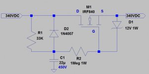
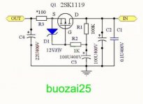
E.g. I recently completed an Audio Note clone ( http://www.diyaudio.com/forums/vendor-s-bazaar/229846-enclosures-diy-3.html#post5262709) where the transformer was 2 x 235V and I could only find 2 x 250V. Just adding two 27 Ohm 5 W resistors in the 250V leads dropped the voltage to the required level. Adding resistors makes it behave more or less (depending on values) like a tube rectifier. The only advantage a tube rectifier has is that the B+ comes slowly online so you have less of an inrush current on the transformer. But the inrush can be controlled by using NTC resistors. You can also control the slow startup with a mosfet filter which is a darn side cheaper than a choke plus it filters a lot better.
I always have a B+ current capability quite a bit larger (50 to 100%) than called for, it keeps the transformer cooler (the Hammonds can run quite warm) and it regulates the voltage better. It also helps the transformer to survive in case of an short in a tube (and when fused properly - NTC's help a lot by making it possbile to use smaller fuses). You do not want to use seperate heater transformers - the smaller the transformer the worse the voltage regulation. Make sure to have your filament voltage +/- 3% of nominal, it helps with longevity of the tube. This is where the Hammonds with their multi taps on the primary can help with adjusting to the correct filament supply. B+ voltage variation has less impact on tube life.
Hammond OPT are a different prospect and I would not touch those with a bargepole. I used Hashimoto in my Audio Note.
Regarding magnetic fields: just be aware on how to orient the transformers versus other transformers or valves, some or more sensitive than others. if you do not know just hook up the mains transformer and rotate the OPT with an AC voltmeter accross the primary. Tetrodes in particular can be problematic, pre-amp tubes can be shielded.
Attachments
Last edited:
With regards to the load capability. The examples they provide are all for solid state diodes, and I plan to use a tube rectifier. Now, I know that a tube rectifier has a significantly larger voltage drop then a SS diode, but does a tube rectifier also impact the current capability?
Hi Tom,
you're comparing a two-way silicon diode rectifier vs. a two-way tube rectifier, don't you? Just because a bridge rectifier is another story with respect to transformer efficiency.
The type of rectification per se won't affect current capability. A given DC current yields from the same AC current in both cases. But: With respect to the higher voltage (i.e. power) losses in HV rectification, you'll either need a bigger transformer (the best, hence preferable solution) or you'll have to wind more turns (for higher AC voltage) onto the same core and bobbin. Thus you'll use thinner magnet wire to cope with the given space. And this, of course, will affect the transformer's current capability.
Best regards!
Calculating the proper type of power transformer is difficult even for experienced builders.
You need to purchase a transformer which is designed for your circuit and labeled to provide the voltage range you want for the type of rectification.
My advice: dual power transformers is very difficult to build and lot of noise and problems can occur. I could never complete an amplifier with 3 power transformers which integrated a dedicated pre-amp and 2 mono for power sections. The ground path always carried hum no matter how I would route it.
Valve rectification is harder to build, it is noisier and you need a bigger transfo. For a start use solid state if you are not comfortable with grounding and tube rolling, some tube rectifiers can make more noise.
Make sure you decouple the vibration noise from the main transformer, it will reach parts of the amplifiers and create noise, even if you cannot feel the vibration it will reach tubes and parts.
 Thread cleaned up, many OT and ad hominem posts removed. Hopefully the thread can return to the worthwhile discussion that was its purpose.
Back to topic.
I get the impression that transformer mechanical noise (laminatios vibrating or what?) forms some aspect of commercial models. Is that true?
To me any commercial transformer with audible (mechanical) noise is unacceptable. How difficult can it be to obviate that?
I get the impression that transformer mechanical noise (laminatios vibrating or what?) forms some aspect of commercial models. Is that true?
To me any commercial transformer with audible (mechanical) noise is unacceptable. How difficult can it be to obviate that?
short answer: glue
brief answer: lamination varnish and a bake out. Requires baking the transformer to above-boiling-water temp; then moving to a vacuum chamber while hot; allowing SIT time to exhaust all volatiles from core and windings. Air mostly, but a surprising amount of hydrocarbons (insulation!) and water vapor. After an amount of time in vacua that is better measured by metrology than a timer, the transformers are plunged into a pool of very thin varnish. The vacuum is released once they're submerged; the inrush of 14.7 lb/in² air strongly forces the varnish into every last inner crevice.
Then they're hauled out, allowed to "drip dry" for another hour. Then off to the drying kiln. Again raised to 80°C, with a lot of blowing air flow. The varnish volatiles percolate out, are wafted away. The varnish hardens. The laminations stop buzzing. Permanently. Same for the windings.
You're welcome.
GoatGuy
Calculating the proper type of power transformer is difficult even for experienced builders.
You need to purchase a transformer which is designed for your circuit and labeled to provide the voltage range you want for the type of rectification.
My advice: dual power transformers is very difficult to build and lot of noise and problems can occur. I could never complete an amplifier with 3 power transformers which integrated a dedicated pre-amp and 2 mono for power sections. The ground path always carried hum no matter how I would route it.
Valve rectification is harder to build, it is noisier and you need a bigger transfo. For a start use solid state if you are not comfortable with grounding and tube rolling, some tube rectifiers can make more noise.
Make sure you decouple the vibration noise from the main transformer, it will reach parts of the amplifiers and create noise, even if you cannot feel the vibration it will reach tubes and parts.
Thanks, but to some of your advice, I call out “balderdash”.
For instance, “a transformer which is designed for your circuit and labeled to provide the voltage range you want for the type of rectification.” This is balderdash, whole.
You need to design circuits based on knowing what solid commercial 'standard' transformers put out. Its that simple. If you have identified (as a for-instance) a handful of Hammond multiple secondary transformers as being "about right", then you need to model out what choosing various versions will do to your 3 to 5 DC supply streams. If you are smart and confident with some circuit complexity in exchange for substantial design flexibility, then regulate the secondaries. Go "all DC", including filament supplies. Shield out the hum mechanically.
Seriously: the freedom that you get is awesome. You decide you need a 290 VDC (very uncommon, but hey…) power section DC supply? Get a 275–0–275 Hammond 270-FX having 173 ma HV winding, 3000 ma at 5 V, 5000 ma at 6.3 V, and get started. Your first-filtered (cap loaded rectifiers) DC will come in at 366 volts. A bit (not too much) LC filtering delivers 350 to regulators. Regulate down the 6 HV supplies independently. 170 for the 2 preamp sections, 220 for the line sections (2), and 2 × 290 V (that strange value) for the output finals.
No need for a custom transformer at all. Especially with regulation. Over 100 dB of ripple reduction. Complete freedom from mains sags, surges, digital noise, etc. Bourne type set-screw stage voltage adjustment, independent of transformer/mains and stage-to-stage interdependence.
That's how its done in the real world. The idea of having a custom mains transformer wound is just silliness: its like specifying palladium plated titanium bodied winches for a tug boat. Pretty, and pretty much useless overkill.
Or as I like to say repeatedly, "regulation young buck, regulation". And I mean the active kind, the multistage kind. It is transformational (wow, the pun is terrible).
GoatGuy
Back to topic.
I get the impression that transformer mechanical noise (laminatios vibrating or what?) forms some aspect of commercial models. Is that true?
To me any commercial transformer with audible (mechanical) noise is unacceptable. How difficult can it be to obviate that?
IMO the keyword here is "commercial".
Virtually all commercial available "off the shelve" transformers are wound with core excitations around 1.6 T.
Completely understandable as this way cost is cut (less material; less weight).
However, with core excitations approaching core saturation, risks are lurking.
Many commercial transformers are mechanically not silent (to put it mildly...).
Apparently the quality of impregnating is insufficient; I am pretty sure that not many commercial transformer companies apply the way of vacuum impregnating the way Goatguy describes as it would make a more expensive transformer.
Besides, high T transformers get rather hot as secondary power is about what the core can deliver.
Last, but maybe not least, strayfields are strongest with high core excitations.
To overcome, or maybe better put, prevent these problems from happening, in my (and others, like Tony) experience it is good practice to choose for lower core excitation; 1T is a nice upper limit.
This lower core excitation however is not so economic: for a power supply transformer with 150VA of secondary power a core of some 300VA is needed
. Winding for lower core excitation requires more primary windings, so the larger winding space of the 300VA core is needed to have enough space for primary and secondary windings (apart from single or multiple screening).At the end of this low T power supply transformer we have the advantages of:
- a cool running transformer (think of nearby electrolytic capacitors not liking heat);
- a transformer with minimal strayfield;
- a mechanically silent transformer (vacuum impregnating still necessary but less critical as the whole thing is less vibrant to begin with).
The story above applies to EI, c-core and toroidal transformers, with some peculiarities typical for the type:
- EI laminations are "loose" after assembling so good quality impregnating is very important;
- c-cores are impregnated during manufacturing, but impregnating still applies to the coil(s);
- toroidal transformers can be a nightmare: prone to core saturation; very difficult to get silent with impregnation as windings tend to be random with much room for vibration.
I don't understand toroidal power supply transformers in (mostly) SS gear as being the norm.
Last edited:
Back to topic.
I get the impression that transformer mechanical noise (laminatios vibrating or what?) forms some aspect of commercial models. Is that true?
To me any commercial transformer with audible (mechanical) noise is unacceptable. How difficult can it be to obviate that?
It helps to use an aluminium chassis and stainless fastening material. In case of Hammond: inspect the bells and check where the the earthing wire of the internal electrostatic shield is attached. Often the bells are not sitting flat against the laminations. I also use silicone AcoustiFeet from SilentPC to stop vibrations from reaching the amplifier and the tubes. AcoustiFeet Vibration-absorbing Low Profile Silicone Feet
AM
Hi,
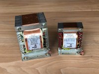
I would like to thank everyone who contributed to this thread. I really learned something and have also found a couple resources I wasn't aware of. After giving it some thought I decided to purchase some transformers from Thomas Mayer. They were in the mail today.
Tom
I would like to thank everyone who contributed to this thread. I really learned something and have also found a couple resources I wasn't aware of. After giving it some thought I decided to purchase some transformers from Thomas Mayer. They were in the mail today.
Tom
Attachments
short answer: glue
brief answer: lamination varnish and a bake out. Requires baking the transformer to above-boiling-water temp; then moving to a vacuum chamber while hot; allowing SIT time to exhaust all volatiles from core and windings. Air mostly, but a surprising amount of hydrocarbons (insulation!) and water vapor. After an amount of time in vacua that is better measured by metrology than a timer, the transformers are plunged into a pool of very thin varnish. The vacuum is released once they're submerged; the inrush of 14.7 lb/in² air strongly forces the varnish into every last inner crevice.
Then they're hauled out, allowed to "drip dry" for another hour. Then off to the drying kiln. Again raised to 80°C, with a lot of blowing air flow. The varnish volatiles percolate out, are wafted away. The varnish hardens. The laminations stop buzzing. Permanently. Same for the windings.
You're welcome.
GoatGuy
as one who designs and builds power transformers, this is how it is done...
you will be surprised to know, electrical varnish have a way of penetrating in between laminations and every nook and crannies in a traffo...
proof? try dismantling a power traffo after it has cured of varnish,
the difference between unvarnished traffo then becomes obvious...
- Status
- This old topic is closed. If you want to reopen this topic, contact a moderator using the "Report Post" button.
- Home
- Amplifiers
- Tubes / Valves
- Power transformer (advise needed)