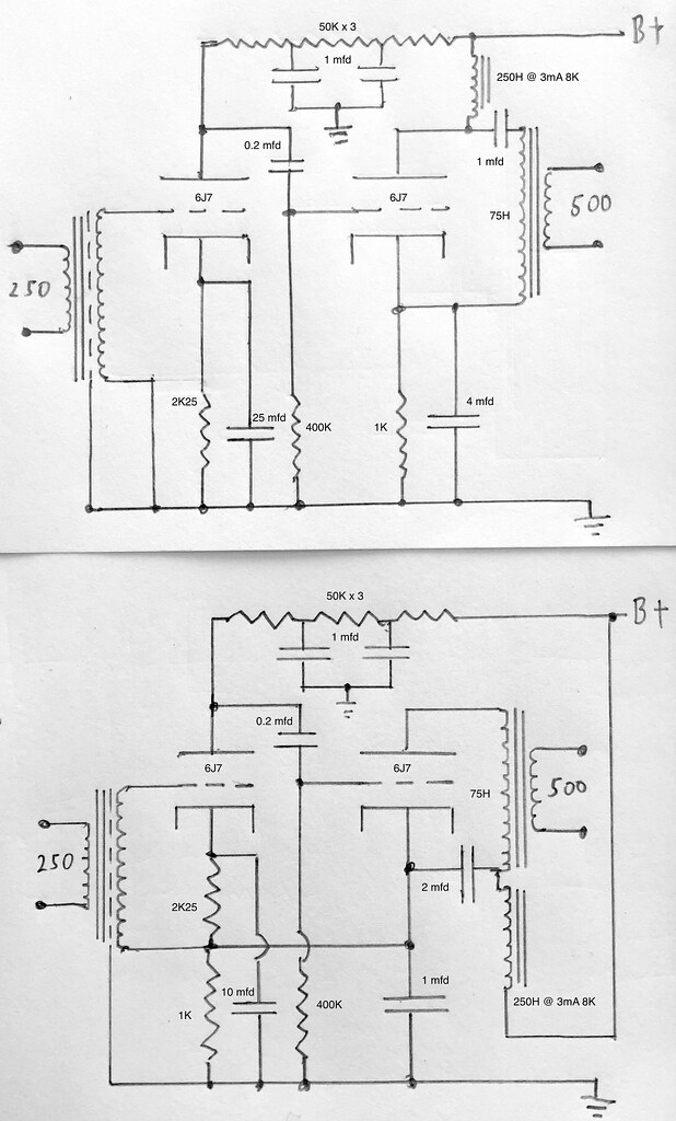
Here's a mid-30's feedback variation I've never seen, along with an output transformer connection variation using the same parts. More or less the same product in different package variations, same specs quoted for both. Pretty closely the same R and C values, 6J7's in triode. The cathode C values and C connection to output primary are higher in the top version, which is slightly later in time, so I am perhaps wrongly for the most part attributing those differences to available C per package size for the years of production.
Curious to see both cathodes stood off the same resistance string in the bottom version, any thoughts there? Were they even thinking of that as feedback, before the Black feedback patent and paper came out? Is the path through the input secondary (3K DR) to grid more significant than the cathode stack, which is 2K25 on top of 1K?
As to the output differences, the choke and output transformer measure the same for DC resistances, about the same for inductance. 8K/250H@3mA on the choke, 940R/75H on the output primary. It seems at face value a radical change to make using essentially the same parts. Thoughts?
Last edited:
The top drawing has the first triode zero biased, while the bottom drawing does not. The top drawing is parallel feed and the bottom drawing is not.
Considering that both cathodes show bypass caps in the bottom drawing that go to ground, I don't see how you're going to get much in the way of feedback through this circuit. You're also required to have higher bias voltage on the first stage compared to the second stage. Is this realistic? It seems likely that you would need to have some cathode bias and some grid leak bias to scratch together a working circuit out of this, though seeing the 500 ohm output suggests gentler tubes that might allow for this.
Considering that both cathodes show bypass caps in the bottom drawing that go to ground, I don't see how you're going to get much in the way of feedback through this circuit. You're also required to have higher bias voltage on the first stage compared to the second stage. Is this realistic? It seems likely that you would need to have some cathode bias and some grid leak bias to scratch together a working circuit out of this, though seeing the 500 ohm output suggests gentler tubes that might allow for this.
I do not see audio feedback, assuming caps are "large" relative to the impedances.
Lower drawing has three low-cuts around a loop. For some value of first-stage gain, it will become an LFO. I think at-best you need gain over 27, so for mid-1930s it is liable to fall short of actual oscillation; check for sub-sonic bumps.
Lower drawing has three low-cuts around a loop. For some value of first-stage gain, it will become an LFO. I think at-best you need gain over 27, so for mid-1930s it is liable to fall short of actual oscillation; check for sub-sonic bumps.
Is the bottom drawing supposed to be series feed and the upper drawing parallel feed? What's the value of the second cap under the cathode of the second tube?
Correct, one is series feed through a choke in addition to the primary, one is parallel feed.
The bottom drawing cathode bypass is 1 mfd. The cap connected between the choke and the transformer primary is 2 mfd.
The top drawing 2nd stage cathode bypass is 4 mfd, and the 1st stage is 25 mfd.
50K 1st stage plate resistor, with the 2 filter caps also being 1 mfd.
Last edited:
I do not see audio feedback, assuming caps are "large" relative to the impedances.
Hmm, OK. I'm incorrect in seeing the path through the input transformer secondary to the grid as feedback from stage 2 cathode? I suppose the answer there is it's bypassed by the cap at stage 2 cathode, BUT that's a 1 mfd so I take it to not cover the entire response range.
Is there some ancient logic in stacking the cathode resistances? I can't think of another example.
- Status
- This old topic is closed. If you want to reopen this topic, contact a moderator using the "Report Post" button.
- Home
- Amplifiers
- Tubes / Valves
- interesting historical feedback and output transformer variation