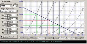
Recalculating the working point
Before buying a new transformer for the power supply, I am thinking to re-calculate the curves to adapt the amplifier to the supply of +203 V that I already have.

If I drop the value of the cathode resistor from 360 Ohm to 200 Ohm, then the current will be about 100 mA and the idle working point -20,6 Volt.
¿What is your opinion?
Before buying a new transformer for the power supply, I am thinking to re-calculate the curves to adapt the amplifier to the supply of +203 V that I already have.
If I drop the value of the cathode resistor from 360 Ohm to 200 Ohm, then the current will be about 100 mA and the idle working point -20,6 Volt.
¿What is your opinion?
Attachments
Hi,
Miguel,
There are a few points in the way you constructed the amp where you're bound to lose some volts:
1/ As said before, the value of the first filter cap is important to obtain the B+ you need.
2/ As you use a different OPT you may also lose some voltage there.
3/ The filter choke may have a different DCR as well.
4/ The 15K dropping resistor could be lowered considerably without affecting ripple too much if needed.
5/ Setting the OP of the KT88 too low you risk to overdrive it causing distortion.
Cheers,")
Before buying a new transformer for the power supply, I am thinking to re-calculate the curves to adapt the amplifier to the supply of +203 V that I already have.
Miguel,
There are a few points in the way you constructed the amp where you're bound to lose some volts:
1/ As said before, the value of the first filter cap is important to obtain the B+ you need.
2/ As you use a different OPT you may also lose some voltage there.
3/ The filter choke may have a different DCR as well.
4/ The 15K dropping resistor could be lowered considerably without affecting ripple too much if needed.
5/ Setting the OP of the KT88 too low you risk to overdrive it causing distortion.
Cheers,
Still confused about how to order a new transformer
Hi Dr. Frank,
I don't know how to calculate the value for a new transformer to compensate this voltage drop and get the desired +375V.
I've been messing with PSUD but I am not even able to simulate the working conditions.
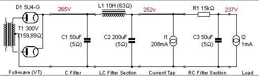
This are the values that I introduce:
T1 = 300V / 159Ohm
C1 = 50 uF
L1 = 10H / 63 Ohm
C2 = 200 uF
I1 = 2x10⁴ mA (In my amp I measure 2x70mA)
R1 = 15 K
C3 = 50 uF
I2 = 1 mA
With this values, PSUD gives me V(C2) = 250 V.
To obtain 375V I have to raise T1 to almost 400V! I know I'm doing something wrong. How do I know the new value for the transformer resistance?
Thank you,
Manuel (not Miguel)
Hi Dr. Frank,
I don't know how to calculate the value for a new transformer to compensate this voltage drop and get the desired +375V.
I've been messing with PSUD but I am not even able to simulate the working conditions.
This are the values that I introduce:
T1 = 300V / 159Ohm
C1 = 50 uF
L1 = 10H / 63 Ohm
C2 = 200 uF
I1 = 2x10⁴ mA (In my amp I measure 2x70mA)
R1 = 15 K
C3 = 50 uF
I2 = 1 mA
With this values, PSUD gives me V(C2) = 250 V.
To obtain 375V I have to raise T1 to almost 400V! I know I'm doing something wrong.
How do I know the new value for the transformer resistance?Thank you,
Manuel (not Miguel)
Attachments
Hi,
Unfortunately I'm not familiar with PSU at all but could it be the transformer rating is just introduced into the soft the wrong way?
Could you try rerunning it with a bigger filter cap after the rectifier? Say,68µF to 100µF for starters.
Are you sure it's seen by the soft as a 300V-CT-300V and not 150V-CT-150 ?
The copper losses of the xformer aren't a big issue, if it delivers the voltage at the current that's specified you'd be O.K.
Cheers,
Unfortunately I'm not familiar with PSU at all but could it be the transformer rating is just introduced into the soft the wrong way?
Could you try rerunning it with a bigger filter cap after the rectifier? Say,68µF to 100µF for starters.
To obtain 375V I have to raise T1 to almost 400V! I know I'm doing something wrong. How do I know the new value for the transformer resistance?
Are you sure it's seen by the soft as a 300V-CT-300V and not 150V-CT-150 ?
The copper losses of the xformer aren't a big issue, if it delivers the voltage at the current that's specified you'd be O.K.
Cheers,
Hola Paco,
It doesn't make much difference at the final result to change the value of this cap from 50 to 100 uF at PSUD
Thanks, I feel better now
Now I am going to measure V and I connecting the components one after the other, so I will now when the V drop occurs.
Cheers,
Could you try rerunning it with a bigger filter cap after the rectifier? Say,68µF to 100µF for starters
It doesn't make much difference at the final result to change the value of this cap from 50 to 100 uF at PSUD
The copper losses of the xformer aren't a big issue, if it delivers the voltage at the current that's specified you'd be O.K.
Thanks, I feel better now
Now I am going to measure V and I connecting the components one after the other, so I will now when the V drop occurs.
Cheers,
Re: Still confused about how to order a new transformer
a couple of observations:
your transformer in PSUD is 300vct with 159ohm source resistance. If you use the edit function for the transformer in PSUD, this works out to a transformer with 16% regulation(probably too high). Assuming 5% regulation, change the transformer values to 315V @ 50 ohms. This will get you up to ~ 325V at the first cap.
To get the rest, you need to switch to SS rectification or a more efficient tube rectifier. PSUD is calculating a large voltage drop for the 5U4G.
Hope this helps.
pete
pingfloid said:
To obtain 375V I have to raise T1 to almost 400V! I know I'm doing something wrong.
a couple of observations:
your transformer in PSUD is 300vct with 159ohm source resistance. If you use the edit function for the transformer in PSUD, this works out to a transformer with 16% regulation(probably too high). Assuming 5% regulation, change the transformer values to 315V @ 50 ohms. This will get you up to ~ 325V at the first cap.
To get the rest, you need to switch to SS rectification or a more efficient tube rectifier. PSUD is calculating a large voltage drop for the 5U4G.
Hope this helps.
pete
In PSUD you can right click the transformer and enter the voltage, current and regulation values and the output voltage and resistance are calculated. Don't worry too much about the program. It is just something to help set up your circuit.
I think you should leave the first filter cap at 50uF to avoid stressing the rectifier. You have the actual measured voltages so you can go from there to set your circuit parameters. You should follow your instinct and lower the cathode resistor of the KT88 to bring up the current a bit. Try a couple of different values and see how it operates electrically, but more importantly how it SOUNDS.
You may loose some dynamic range with a lower voltage on the plate so you have to experiment a little to see where you can ballance things out. Varying the cathode resistor to change the bias point is about the only thing you can do at this point without a major, costly redesign. Your power supply transformer is not giving you what you asked for but what you have may not be so bad. Listen to it awhile and decide.
I don't know if it will matter but you may try a higher value than 68k for the grid resistor on the KT88.
Thomas
your transformer in PSUD is 300vct with 159ohm source resistance. If you use the edit function for the transformer in PSUD, this works out to a transformer with 16% regulation(probably too high).
159 Ohm is the result from the following actual measures:
Primary Supply Voltage: 220V
Primary resistance: 8,4 Ohm
Secondary off-load voltage: 312V
Secondary resistance: 143 Ohm.
Then I introduce this values at the "Source Impedance Calculator" editor of PSUD and I have the result of 159,89 Ohm. You are right: this correspond to a 16% regulation, but that are the real values that I measure from the transformer. So maybe my transformer really have this high regulation tolerance. (I didn't specify that when I did order it). Is it usual to tell the manufacturer the desired regulation of the transformer, or maybe the expected impedance?
you need to switch to SS rectification or a more efficient tube rectifier
Ok, I'll experiment with a couple of 1N4007
Try a couple of different values and see how it operates electrically, but more importantly how it SOUNDS.
Yeah, It sound good to me from the beginning! Even when I had the little oscillation at some positions of the volume pot the sound was not bad
Now I just want to balance the electrical behaviour and see if it can improve the sound.Thank you very much for your help
bridge anyone?
Hi,
I kind of hate to bring it up, but if you go for SS rectification you could try a bridge instead of a full wave. With choke input that should give you about 425V after the filter. Or you could go with a hybrid bridge with two SS diodes and two tubes (or maybe one with separate cathodes?) for something a bit lower. Just something to kick around
Michael
Here are my measures, connecting the components step by step:
1 - Transformer only: 316 + 316 V DC
2 - 5U4G: +300V
3 - 5U4G + 50uF (C1): +432V
4 - 5U4G + 50uF (C1) + choke + 200 uF (C2): +433V
5 - Connecting the KT88: +323V / 72 mA
At step n. 5 (when the load is connected) there are small sparks at the 5U4G at the instant of switching on, and constant interferences at my computer monitor.
Finally I have tried with two cold SS diodes and I get +392V (+366V for stereo version). There are no interferences at the monitor, but the speakers receive a low frequency shock when powering on. Anyway, I love the bottlehead tube, so I will order a 340+340V transformer and I'll think about how to get rid of the interference at the monitor.
The two KT88 get very very hot only in few minutes (with no input signal), but I suppose it's normal (my previous experience is limited to Push Pull designs).
Cheers,
Manuel
1 - Transformer only: 316 + 316 V DC
2 - 5U4G: +300V
3 - 5U4G + 50uF (C1): +432V
4 - 5U4G + 50uF (C1) + choke + 200 uF (C2): +433V
5 - Connecting the KT88: +323V / 72 mA
At step n. 5 (when the load is connected) there are small sparks at the 5U4G at the instant of switching on, and constant interferences at my computer monitor.
Finally I have tried with two cold SS diodes and I get +392V (+366V for stereo version). There are no interferences at the monitor, but the speakers receive a low frequency shock when powering on. Anyway, I love the bottlehead tube, so I will order a 340+340V transformer and I'll think about how to get rid of the interference at the monitor.
The two KT88 get very very hot only in few minutes (with no input signal),
but I suppose it's normal (my previous experience is limited to Push Pull designs).Cheers,
Manuel
Manuel,
I am no tube expert, but the combination of factors you describe suggest that maybe the output tubes draw too much current: they get very hot, the voltage drop is quite large I think, and the sparks at the rect tube suggest also overload. Of course, the sparks cause the monitor interface, so once you fix the amp, that will be gone. I doubt that a different power xformer fixes this. Using a higher volt transformer may aggravate the problem. I would take a hard and long look at the bias conditions at the output tube.
Jan Didden
PS This may have been covered north of this post, but I was too lazy to review the whole thread....
Hi Jan,
The output tubes are drawing 72 mA each (67mA at the plate, 5mA from the 2nd grid connected to the 40% tap). At the original design with the Tango OT transformer they are supposed to eat a little more current: 104 mA each
The cathode voltage is +29,3V. (+37,5 at the original design)
I don't understand how this 72 mA can produce the voltage drop and the sparks
Tomorrow I'll borrow a thermomether to check the valves. Any idea about the normal temperature conditions?
Am I the only one?
One question:
Have some of you built the Hiraga's amp? Maybe using the Tango OT?
I am wondering why with the 5U4G the voltage drops from +433 to +323 when applying the 42mA load, and with the SS diodes it drops only to +322 when applying the same load. Could the 5U4G be damaged? It is supposed to admit this load. And the interferences at the monitor do not appear anymore with the SS diodes.
Cheers
and with the SS diodes it drops only to +322
... with the silicon diodes drops to +392V
My brain needs some sugar
The 5U4 is supposed to drop 40V at 255mA current draw. Yours is dropping 69v more than SS rectifier or 110v total. This drop and the sparks you see indicate a problem with your rectifier is a liklyhood. If you have another 5U4 to try, swap them. If not, use SS until you get one if you want to stick with valve rectifiers.
Yoy mentioned your KT88 gets hot. Do the plates get red? I would not think so with 72mA through the tube unless the oscillation is back.
Thomas
Yoy mentioned your KT88 gets hot. Do the plates get red? I would not think so with 72mA through the tube unless the oscillation is back.
Thomas
Heats faster than my breakfast toaster
Hi Thomas,
The 5U4G only cost 18 Euro, so I will try with a new one.
I've read that the GZ34 / 5AR4-STR can substitute the 5U4G. Is there any advantage?
The plates of the KT88 do not get red, but It is impossible to touch them after 1 minute of powering on (before rising the supply to 366V I could do a hand massage to them for a long time)
I've checked with a scope and I see no trace of HF oscillation. My scope is a portable Velleman 10MHz/0,1 mV max. I suppose it's enough. I am taking measures from all the points at the path of the signal, including the speaker output, sith no input signal applied. Is it the correct way to check it?
Thank you very much
5U4G4 Vs GZ34
I've been doing a little research:
....................................5U4G / GZ34
Heater Voltage .............. 5.0 V / 5.0 V
Current ......................... 3.0 A / 1,9 A
max AC Plate Supply ....... 450 V / 550 V
I max:............................ 245 mA / 250 mA (at 300 + 300 V)
Input capacitor max:........ 40 uF / 60 uF
Tube drop.............. 44V @ 225mA / ??
The 5AR4 has the same pin out as the 5U4 so it can be directly substituted. The 5AR4 is indirectly heated and takes a bit less heater current (1.9A). The voltage drop can be as much as 50v though.
Since you don't detect any HF oscillation I suspect you have a defective 5U4. I have no direct experience with KT88 but their cousin, 6550 get too hot to touch as well. as long as they are operating within their specifications they are OK. Make sure you have adequate ventilation so heat buildup is noy a problem.
Thomas
- Status
- This old topic is closed. If you want to reopen this topic, contact a moderator using the "Report Post" button.
- Home
- Amplifiers
- Tubes / Valves
- High frecuency oscillation when moving volume pot