Hi,
Regarding to the issue about 6X5 heater cathode shorts melting the transformer:
1. What causing it? I heard: that its related to the physical structure of the rectifier itself (heater cathode separated to close), not properly designed power supply especially regarding the impedance (or resistance??) of the secondaries power transformer to plate which also related to the value of 1st C input filter (maximum 40uf, typically 4uf), too high DC voltage handled by the rectifier causing leakage heater cathode, as indirect heated rectifier it cant tolerate high reverse voltage, some even say it caused by rectifier plate to plate or plate to cathode shorts.
2. What is the solution if still want to use them? (honestly i recently got the 6X5GT failure experience)
Thank you.
Regards,
Roy
Use a dedicated filament winding and tie the cathode of the 6X5 directly to it, no potential difference, no cathode insulation break down issue. (Make sure the filament winding you use is rated for more than the highest voltage possible at the cathode of the 6X5 under high line, and before the other tubes start to draw appreciable load current)
You can also add a UF4007 or similar high PIV diode in series with each plate as is commonly done with the 5AR4.
You can also add a UF4007 or similar high PIV diode in series with each plate as is commonly done with the 5AR4.
I have pieces of test equipment that use the 6X5 and have had zero failures. However, they designed the supply with recommended capacitance and resistance in line. That is the other spec that wasn't mentioned, minimum plate resistance. The power transformer makes some of this up.
If you drew enough current to wipe out the transformer, why didn't the line fuse blow?
-Chris
If you drew enough current to wipe out the transformer, why didn't the line fuse blow?
-Chris
Use a dedicated filament winding and tie the cathode of the 6X5 directly to it, no potential difference, no cathode insulation break down issue. (Make sure the filament winding you use is rated for more than the highest voltage possible at the cathode of the 6X5 under high line, and before the other tubes start to draw appreciable load current)
You can also add a UF4007 or similar high PIV diode in series with each plate as is commonly done with the 5AR4.
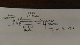
Is my draw wiring correct? I use separate transformer for heater, it has dual secondaries, one for the 6SN7GTA preamp, else the rectifier. Each secondaries winding rated for 2 amperes, its large enough right? ( i will use them to supply single stage 6SN7GTA with 300VDC HV). What is the function of UF4007 in series with each plate of 6X5GT?
Where did you get the 40uF maximum from? The only datasheet I found that listed it said 32uF.
It's an 80mA rectifier. If you need to go bigger and have heater current capacity, the 6AX5 goes to 125 mA.
fuse the heater winding
I do have many 6X5GT now, if its ok to use them, i want to still use them, the current for the HV is enough for single stage preamp of 6SN7GTA right? The 40uf is noted in Tung Sol datasheet, i do find each manufacturers have a little difference in mentioning C input notes, but basicly it have the same information to take precaution of the current surge from the transformer secondaries.
I have pieces of test equipment that use the 6X5 and have had zero failures. However, they designed the supply with recommended capacitance and resistance in line. That is the other spec that wasn't mentioned, minimum plate resistance. The power transformer makes some of this up.
If you drew enough current to wipe out the transformer, why didn't the line fuse blow?
-Chris
if it is like the SX 780 transformer, most of the power is not delivered on a single winding.
therefore if that winding shorts, it may melt and short with itself or adjacent windings before the line fuse blows
Well, over heating and melting is not an instant thing unless very high energy is involved (lightning for example). Under normal circumstances, the HT winding doesn't draw a lot of current, but in fault mode you might be surprised.
-Chris
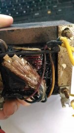
Just like what happened before on my preamp, i do test my new RCA 6X5GT, for about 8 seconds from i turn it on, i saw a some archs in the filament of the rectifier, so i turn it off. check the pin of the rectifier everthing is still ok, but physically notice the rectifier filament have some shiny parts as like it was scratched. Then i decided to use my daily used rectifier, there is humm coming out, try to replugging the rectifier and 6SN7GTA, there is no change. Then i smell burn out thing, turn off the amplifier and preamp, unplug the main cable, i touch the wood case of the transformer its warmer than usually. Decided to open the preamp, and find out the high voltage secondaries being short, 0 resistance in the winding, and find the out layer of the transformer melted. The main fuse is still ok. But i do find the C input of my preamp is to much bigger than the maximum, 180uf...
Attachments
Use a dedicated filament winding and tie the cathode of the 6X5 directly to it, no potential difference, no cathode insulation break down issue. (Make sure the filament winding you use is rated for more than the highest voltage possible at the cathode of the 6X5 under high line, and before the other tubes start to draw appreciable load current)
Strange. As the maximum heater to cathode voltage rating is 450 Vdc, there shouldn't be expected any issue, unless this and/or the maximum filter capacitor value ratings are violated. The 6X5 clearly appears to be designed to be operated from the same heater supply as the other tubes in the device. Maybe the specific tube itself was faulty? Tying the cathode to the heater eradicates the possibility of an issue here, of course.
You can also add a UF4007 or similar high PIV diode in series with each plate as is commonly done with the 5AR4.
Really, and why? Maybe because a recent make's 5AR4 manufacturing quality hasn't too much in common with that of an original Philips/Mullard tube?
Best regards!
Hi sutantoroy,
What you are seeing is a classic failure due to excessive capacitance. Use a little lower capacitance than the maximum for starters. Then, pay attention to the minimum plate resistance specification as well. If you have to add resistors, that's fine. Manufacturers have done that in their designs for ages.
The lower capacitance will allow a higher amount of ripple on the DC line, but that beats the higher frequency pulses that the high capacitance will generate. The lower frequency ripple is a lot easier to get rid of with a regulator than the high frequency hash created when capacitance is too high.
-Chris
Hi sutantoroy,
What you are seeing is a classic failure due to excessive capacitance. Use a little lower capacitance than the maximum for starters. Then, pay attention to the minimum plate resistance specification as well. If you have to add resistors, that's fine. Manufacturers have done that in their designs for ages.
The lower capacitance will allow a higher amount of ripple on the DC line, but that beats the higher frequency pulses that the high capacitance will generate. The lower frequency ripple is a lot easier to get rid of with a regulator than the high frequency hash created when capacitance is too high.
-Chris
Thank you Chris. So, what do you think about separate secondaries winding for rectifier heater and tying the heater pin to cathode, is it necessary doing that? What is the side effect by doing that (tying the heater pin with the cahode)
Regards,
Roy
Hi Roy,
That all depends on the rectifier you are using. Normal heater-cathode breakdown is on the order of 100 ~ 200 VDC (either polarity, peak). Some rectifier tubes were designed with very large heater to cathode voltage tolerance, so they could be run off the same heater line as all the other tubes (in this case, 6X5 has a breakdown of 450 VDC). That means that you can run this tube from a ground referenced heater line with all the other tubes as long as that potential difference remains below 450 V peak.
Tubes that use a filament like a 5U4 must run a separate filament winding that is at the same potential as your B+ supply. This one needs 5 V at 3 amperes. That is why you will see tube power transformers that commonly have a 5 VAC winding good for 2~3 amperes.
So, your power supply does not require you to run your rectifier tube off a separate winding. You can even float your entire heater supply up to 30 ~ 50 VDC to reduce hum if you want with zero ill effects for the 6X5.
-Chris
Hi Roy,
That all depends on the rectifier you are using. Normal heater-cathode breakdown is on the order of 100 ~ 200 VDC (either polarity, peak). Some rectifier tubes were designed with very large heater to cathode voltage tolerance, so they could be run off the same heater line as all the other tubes (in this case, 6X5 has a breakdown of 450 VDC). That means that you can run this tube from a ground referenced heater line with all the other tubes as long as that potential difference remains below 450 V peak.
Tubes that use a filament like a 5U4 must run a separate filament winding that is at the same potential as your B+ supply. This one needs 5 V at 3 amperes. That is why you will see tube power transformers that commonly have a 5 VAC winding good for 2~3 amperes.
So, your power supply does not reuqire you to run your rectifier tube off a separate winding. You can even float your entire heater supply up to 30 ~ 50 VDC to reduce hum if you want with zero ill effects for the 6X5.
-Chris
Thank you again Chris. To make sure that i do get know what you are telling, so i can connect the heater pin to ground reference or just leaving it not connected to the ground reference (leaving the transformer secondaries heater winding just connected to the tube heater pin, no conection to the ground reference). Both is ok, is it right?
For the kind like 5U4 (is it called direct current rectifier?), the reason it needs separate winding is it because the current requirement for the rectifier heater is relatively very high to other tubes or other electrodes current capacity, so it can be a very high inrush current damaging other electrodes. By doing separate qualified winding will likely as current manufacturer which is supplying the rectifier heater high current demand, is it right?
Regards,
Roy
Hi Roy,
You can ground the centre tap of the heater winding. Here it is a question of background hum, so try floating it, grounding it and floating it to a specific voltage below say - 50 VDC. Make sure you have at least a 10 uF capacitor to ground if you tie the heaters to some voltage above ground.
A filament tube like the 5U4 has it's filament at full raw B+ potential. This is by design and you can't escape that connection. Have a look at a schematic to see what I am saying. Since this must be so, the filament does require its own dedicated winding. Just remember that in these tubes, the "heater" is combined with the cathode to make it a filament.
-Chris
Roy, the heater for a rectifier valve needs to be tied to some potential, not left floating.so i can connect the heater pin to ground reference or just leaving it not connected to the ground reference (leaving the transformer secondaries heater winding just connected to the tube heater pin, no conection to the ground reference).
For directly heated cathode rectifiers (such as 5U4), where the cathode is the heater, then one end of the cathode/heater is connected to (typically) the first filter cap positive terminal (typically B+), which has a defined voltage relative to 0V ground.
For indirectly heated cathode rectifiers (such as 6X5), the heater has to still be connected to a defined reference potential - which could be 0V, or an elevated DC voltage (as when trying to minimise hum, or due to the circuit having valves with cathodes that are at a high DC voltage), or to the rectifier's cathode (such as when a separate heater winding is just being used for that rectifier valve's heater supply).
For indirectly heated cathodes, the datasheet shows the voltage difference that allowed to be applied between heater and cathode.
Last edited:
Hi trobbins,
The 6X5 with it's 450 Vpk H-K rating is designed to share the heater power with the rest of the tubes in the device. I've never seen signal tubes left floating, but I can't imagine anything untoward would happen to a 6X5 that had an unreferenced heater source. We don't like the idea, but I doubt there would be any repercussions if you let it float completely. Leakage current would do that job for you anyway (reference the heater to some voltage, probably B+).
-Chris
Hi Chris, yes I agree with your view on what would likely happen with an unconnected heater. For forum chit-chat I'd prefer to present a more clear-cut path for diyers as the concept of a floating circuit would likely be new to many, along with reconciling what could happen and what some docs (such as safety standards) dictate as to how to interpret what insulation etc to apply for such a floating circuit.
From a practical perspective, the configuration that minimises heater-cathode voltage difference is likely to reduce quirky processes that are not too definable, such as how heater-cathode resistance changes over time.
Ciao, Tim
From a practical perspective, the configuration that minimises heater-cathode voltage difference is likely to reduce quirky processes that are not too definable, such as how heater-cathode resistance changes over time.
Ciao, Tim
Hi Tim,
You have that right! I've studied various forms of heater-cathode insulation failure. The topic was well written up way back in time. Only zero potential difference may avoid that fate, or an early open heater.
Ever see an arc between the heater and cathode? I have, and not in a rectifier tube either. It's very dramatic and results in a dead tube very quickly.
-Chris
I found it interesting reading the 1962 RCA digest of papers, and the onerous process of identifying impurities and processing/purity requirements of heater coating, and the investigations of metal migration, and the physical jostling that goes on during turn-on/off between moveable heater and fixed cathode tube. No wonder there is such a wide distribution of heater-cathode resistance found in vintage signal tubes.
I recall a failed PT from what appeared to be 6X5 failure - I'll have to look up my notes on that one.
Was the arc in an output tube from pin 2-3 connection?
I recall a failed PT from what appeared to be 6X5 failure - I'll have to look up my notes on that one.
Was the arc in an output tube from pin 2-3 connection?
- Status
- This old topic is closed. If you want to reopen this topic, contact a moderator using the "Report Post" button.
- Home
- Amplifiers
- Tubes / Valves
- Is 6X5GT prone to failure?