It is, IMHO, VERY useful to know how to figure this stuff by hand.
This is a quote worth remembering. Another is, that the design of power supplies used to be done every day, day in and day out, on slide-rules.
There's no need for 5 significant figures of precision. Hardly, for 3. The heuristics of building a power supply must accommodate at least 1 order of magnitude variation in moment-to-moment current demand. Actually closer to 2 OoM.
And PS designing for HV supplies is really not hard.
Transformer secondary
[1] → rectification
[2] → → first capacitor ("hold the peaks, fill the valleys")
[3] → → → inductor ("zap HF especially, but some ripple too")
[4] → → → → capacitor ("the big reservoir")
up to [4], and you have a perfectly acceptable HV supply for the FINALS stage. It offers brilliantly low impedance in audio frequency bands. Its simple. Its components need not be expensive. Its durable. It works. NO REGULATION either, except all these components working to smooth the flow.
For the pre-final stages (all of them), I definitely hedge toward a separate regulated supply.
Transformer secondary
[1] → rectification
[2] → → first capacitor ("hold the peaks, fill the valleys")
[3] → → → inductor ("zap HF especially, but some ripple too")
[4] → → → → capacitor ("the smallish reservoir")
[5] → → → → → regulator
[6] → → → → → → backflow gate (rectifier)
[7] → → → → → → → capacitor ("biggish" reservoir)
It doesn't much matter whether there is a second hi-volt secondary on the transformer or not: if there are HV sags due to the finals sucking up significant power on transients, that affects ALL of the power transformer's windings. You'd actually need a separate HV transformer to get past that. But no matter: decent power supply RESERVOIR planning, and all those little demand earthquakes are made quite invisible. By design.
Stages 4 thru 7 are key. The "backflow gate" is a simple rectifier to prevent induced over-voltage from hitting the output of the regulator. Just a safety device. The REGULATOR [step 5] can be almost anything, although I prefer such simple things as the TIP–50 500 volt NPN transistor. And Zener diodes (in chains) to make up whatever "precise" voltage matches your design fancy.
Such low-power, high-volt supplies are mouse-quiet. And they don't cost a bundle to make. And they work for decades. My definition of a great supply.
ALL OF THIS can be done "on a napkin, with a slide rule" (tho' not many of us have them OR remember how to use them). But its pretty simple - estimate voltages and current, then choose components that deliver the performance needed, with room to spare. Finally breadboard the supply on the bench. Carefully. And buy a nice bunch of 10 watt 33 kΩ or 100 kΩ resistors to cobble together into a high-volt load. Remember E = I R to work out amps. And P = I E … = I² R = E²/R to calculate resistor power dissipation.
And buy an oscilloscope. $100 bucks gets you a perfectly workable scope. Get nice 10× probes (maybe another $100), so that your scope system is protected from the high volt side. And a decent "old school" needle voltmeter. You wouldn't believe how useful seeing "the needle swing" is in doing PS work. I get a feel for the value just by glancing. Good, cheap meters are a dime-a-dozen on Ebay. For example
Vintage Triplett Volt- Ohm Milliammeter Model 630 PLK TESTED | eBay
I would have died and gone to heaven in 1970 had I been able to afford that Classic. Well, I didn't die, but I got one and what … some 45 years later, its still working. Occasionally I have to replace the quad of AA batteries it likes. About once every couple of years. In fact, I have 4 of them now. Got the last 3 on Ebay. When you are doing PS and HV work, its nice to have many test instruments at hand. (PS: get instrumentation hook-spring clips).
SORRY FOLKS for writing so much. Its just that the younger crowd, completely lavished with near-infinitely powerful computing at their fingertips, has yet to get out from behind the computer and just do bench breadboarding. Where you learn the empiricals.
Sorry.
GoatGuy
I second on TIP50 filter. Cheap, simple, and reliable as a brick. While the mosfet provides kinda better filtering it does not tolerate any offending. The TIP50 would put up almost with any accident.
To make it easier and to to the point for "younger crowds" ))Remember E = I R to work out amps. And P = I E … = I² R = E²/R to calculate resistor power dissipation.
Attachments
To make it easier and to to the point for "younger crowds" ))
It's good to know that while some old goats bemoan the 'younger crowd' (whoever they are - as a man already over the hill, I'd be happy to be counted among them
") ), others are willing to help, although I suspect your tongue might be firmly wedged in your cheek...
), others are willing to help, although I suspect your tongue might be firmly wedged in your cheek...In all seriousness, that diagram joins up a lot of the dots, for which I thank you.
Perhaps it was standard fare back in the day; if you'd been compelled to study the GCSE curriculum, you'd understand why it's new to me...
Matt.
Khe-m. .. just keep in mind: without some "wedged tongues" you won't find another useful diagram shared here. .. either this or that.
Both my competed projects at DIYA were of original non-of-copy-pasting stuff, and there is smth else brewing up. .. though I completely missed the tube era in its prime. Yeah, one of e-eh. .. semi-younger crowds ))
Both my competed projects at DIYA were of original non-of-copy-pasting stuff, and there is smth else brewing up. .. though I completely missed the tube era in its prime. Yeah, one of e-eh. .. semi-younger crowds ))
...the output transformer - especially in a SE design - is itself quite a filter. it does a good job isolating any unfiltered-out power supply hum from the plate of the EL–34 (or whatever) final tube. Nature of inductors....
Actually, no.
If it intercepts buzz, it couples it right to the output.
This is a serious problem with triode power. Over 2/3 of the B+ buzz appears across the OT. Because triode plate is low impedance, 1/2 to 1/4 of the optimum load.
It is much less a problem in pentodes. Because pentode plate impedance is high. Typically 10X the happy load. So only 1/10th of B+ buzz is impressed on the OT. This is an additional reason power pentodes swept the field when they became available.
{source omitted} said:....can be done "on a napkin, with a slide rule" (tho' not many of us have them OR remember how to use them).
How To Use Your Napkin When Dining
Power supply transformer should be 450-0-450 to deliver the voltage shown with choke input. (not 225-0-225). PSUD uses the half-winding voltage (and DCR) for a full-wave rectifier. All is not lost if you've bought or ordered the transformer - a full-wave hybrid bridge can be used (two silicon diodes, plus tube rectifier(s)). no connection to the center-tap.
I mean, beside the nice dual 300B, the fact the tube is driven by an interstage.
This will help isolate the driver stage, maximize gain and linearize the input tube signal.
You get more power from the 300B, one of the most linear tube ever.
A practical example from a beginner for your consideration.
I just finished building a test bench parallel EL34 with 12AT7 input. Transformer is Hammond 372HX 600v CT, 230 ma. SS rectifier with CLC filter; 50uF + 5H, 150ohm + 470uF.
With 2 EL34's at 60ma each (120ma) B+ is about 365v
With 4 EL34's at 50ma each (200ma) B+ is about 320v.
Notice that the B+ is about 1.1 to 1.2 times transformer rating.
Incidentally the PSUD model matches this result using the unloaded voltage (325v) and twice output resistance from spec sheet.
With your proposed 180-0-180v transformer you are probably looking at about 220v at the most; maybe 200v with tube rectifier.
A 600 or 650v CT transformer may be a better choice depending on rating, load and type of rectifier. Please confirm for yourself though as my experience is limited.
I second on TIP50 filter. Cheap, simple, and reliable as a brick. While the mosfet provides kinda better filtering it does not tolerate any offending. The TIP50 would put up almost with any accident.
To make it easier and to to the point for "younger crowds" ))
Thanks. I keep forgetting that most everyone (except a lot of us DIY goats) have completely forgotten their algebra skills. With
E = I R you easily rearrange to:
I = E/R and
R = E/I
With
P = I E you easily rearrange to:
I = P/E and
E = P/I
With substitutions…
P = I E and bringing in E = IR
P = I I R …
P = I² R or bringing in I = E/R
P = E/R E …
P = E²/R again from diagrams. And working with those two…
P = E²/R rearranging to find E
E = √( PR ) or starting with
P = I² R rearranging to find I
I = √( P/R )
None of these are to show "mental superiority", but just how EASY it is - if you can only remember 2 formulæ, and a bit of algebra - in deriving EVERY one of the equations on that nice diagram … without resorting to more than memory and a few seconds scribbling on the back of a paper napkin.
And the point there: It is so much more useful to have a tool-at-hand, than one across the lake, at the dock, in the foot locker, under 3 seasons of tarps, detritus, bird droppings and rust accumulation. EVEN if the tool at hand requires a bit of algebra and one's memory.
E = I R "See? no SIR!"
P = I E "its as easy as pie"
Lastly the answer to the oft-asked question, “So Goat, why don't they use V for volts and A for amps, W for watts and O for Ω?” Because those are the units of the electrical terms. But to whit, W = VA is so commonly used by electrical contractors, that we measure most AC inductive devices in terms of their VA rating. Our freshly installed pole transformer proudly says "50 KVA" on the front face. 6 inch tall letters. an insiders term. V = AO however hasn't gotten the same traction.
GoatGuy
I second on TIP50 filter. Cheap, simple, and reliable as a brick. While the mosfet provides kinda better filtering it does not tolerate any offending. The TIP50 would put up almost with any accident.
PS … ... ... we really agree on this, friend. While one can imagine any number of ingenious ways to use a tough-as-nails NPN as a pass (series) regulator, the emitter-follower is intrinsically trivial to do.
And in this regard, I like (because they're so darn cheap) to use a cascade of them. Make a resistor chain:
VUNREG = 385 V
RTOP = 2.2 kΩ (340 V)
RMID = 1.0 kΩ (320 V)
RLOW = 1.0 kΩ (300 V)
RBOT = 15 kΩ
The Thevenin equivalent impedance (Kirchoff's laws, etc) combined with an hFE of 25 or so for an "O" bin TIP–50 yields a 2 volt drop on the 340 V tap, a 1.8 volt drop on the 320 tap, a 0.9 V drop on the 300 tap. Input currents to the BASE of each TIP–50 emitter follower. Nice small caps (10 μF) gets the leveling in place.
One could build all that on a small circuit board what, 2 square inches? With operating (output) loads of 27 ma (340 V), 17 ma (320 V) and 7 ma (300 V), the TIP–50s should have tiny heat sinks. less than 2 watt dissipation, per.
Anyway yes. I am a firm believer in E = IR and P = IE, and the utility "in the modern sense" of using spreadsheets to figure out the math. (That's where these values, above, came from. It took about 3 minutes to cobble together. No circuit, sim, drawing, mistake-editing needed.)
GoatGuy
Good evening,Thanks. I keep forgetting that most everyone (except a lot of us DIY goats) have completely forgotten their algebra skills. With
E = I R you easily rearrange to:
I = E/R and
R = E/I
etc...
GoatGuy
I'm not sure if you're directing this specifically at me, or at people in general...
If the latter (and having re-read my previous response to shef), it occurs that I may have given the impression I'm ignorant of these formulae, which is not the case, I just hadn't seen them coralled in so handy a fashion
. I've spent time on a fair few audio forums over the years, I won't need to tell you that most of what is bandied about is utter guff (especially in any guitar related forum, which as a guitarist I'm guilty of visiting). It doesn't take long to work out who knows what they're talking about and who doesn't.
As a relative newcomer to diyAudio, I've been impressed not only by the number of people who obviously (and demonstrably) know their onions, but also how well they know them and how willing they are to share that information. It's a breath of fresh air.
Getting to my point, I'm obviously new to designing/building hi-fi audio. In spite of what you may think, I'm not the sort of person who expects to have it all spelt out for him. I've been doing my best to put in the hours and learn the theory behind the circuit (indeed I write V=IR in the top right hand corner every page
), but my brain is not naturally mathematically inclined, and it's been slow going.Nevertheless, it's safe to say I've done more maths over the past few weeks/months than I ever did in school, and have learned more to boot.
With regards to my difficulties designing my power supply, it was as I struggled through the maths in Morgan Jones that he informed me (and I paraphrase) 'nowadays we'd just plug the numbers into PSUD2'. Seeems I'd have been better off using pen and paper, or as others have suggested testing the supply on the bench.
Long (dull
) story short, I've spent most of the weekend doing just that, and while I'm no closer to a finished design, I think I've learned something. Exactly what, remains to be seen...Matt
Last edited:
....Hammond 372HX 600v CT, 230 ma. ....the PSUD model matches this result using the unloaded voltage (325v) and twice output resistance from spec sheet.....
The real series resistance would include the DCR of the 120/240V *primary*, as reflected by the voltage ratio.
That's hard math, and 3X harder because 372HX has three significant outputs.
A "perfectly optimum" design would use the same pounds of Copper on primary and secondary(s), just different gauges to get the right turns count for the desired ratios.
And then, ignoring ratios, the effective secondary resistance is indeed double the secondary resistance alone, because the primary resistance will reflect-across as the same value.
Let's check. For simplicity, take primary wired 240V. Secondary is 651r. Primary is 7.7r resistance. This reflects as the *square* of the voltage ratio. 651/240 is 2.7. 2.7 squared is 7.36. 7.7r at primary reflects as 57r added to secondary. Sec alone is 77r. So just like that, it is not quite "double". However there are two more load-rated windings, which the primary has to supply. Adjusting for the 651V winding being about 138VA of a 190VA total load, we get primary resistance "just to power the 651V winding" of 79r, which indeed makes "double" the 77r of the sec alone.
It rarely works out this close. Wire only comes in set gauges, we always round-up/down from ideal #31.2 to available #30 or #32. We like to find turn-per-layer which fills the whole width so the winding is not lop-sided or wastes available space. High volt windings may need more insulation (a 10KV winding may be >50% varnish and paper).
Progress, of sorts...
Afternoon all,
Progress has been made over the festive period, although not all of it in the right direction.
Having finally arrived at a design I thought might be a worthwhile starting point, I sat down and totted up the cost. At this pint, quickly realised that to make the project worth embarking on would cost far more than I anticipated and - more importantly - more than I have to spend.
As a result, I'm shelving the project for the time being, until I have amassed enough:
A: Money
and
B: Knowledge
to make it a success, which I don't think in all honesty it would have been had I continued with it at present.
I'd like to thank everyone for their help and advice along the way, and indeed apologise for having wasted your time. I suspect a lot of that advice will find it's way into the final project, however far down the road that may be...
On a more positive note, I haven't been idle. I've traded the SET for a simpler, cheaper 'parts drawer' design, running EL84's as pentodes for around 4 Watts per channel.
I'll start a new thread for that soon, any help will be greatly appreciated.
Thanks again,
Matt.
Afternoon all,
Progress has been made over the festive period, although not all of it in the right direction.
Having finally arrived at a design I thought might be a worthwhile starting point, I sat down and totted up the cost. At this pint, quickly realised that to make the project worth embarking on would cost far more than I anticipated and - more importantly - more than I have to spend.
As a result, I'm shelving the project for the time being, until I have amassed enough:
A: Money
and
B: Knowledge
to make it a success, which I don't think in all honesty it would have been had I continued with it at present.
I'd like to thank everyone for their help and advice along the way, and indeed apologise for having wasted your time. I suspect a lot of that advice will find it's way into the final project, however far down the road that may be...
On a more positive note, I haven't been idle. I've traded the SET for a simpler, cheaper 'parts drawer' design, running EL84's as pentodes for around 4 Watts per channel.
I'll start a new thread for that soon, any help will be greatly appreciated
.Thanks again,
Matt.
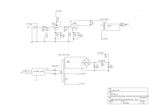
This tread was not for nothing. I was trying to design a similar amp as you and it helped me to get to this design . I don't know if i'm going to build it. I would like to simulate it before i try, but i don't know how to do that...
Did i make obvious mistakes? And how do you simulate this?
. I don't know if i'm going to build it. I would like to simulate it before i try, but i don't know how to do that...Did i make obvious mistakes? And how do you simulate this?
Attachments
This tread was not for nothing. I was trying to design a similar amp as you and it helped me to get to this design
Did i make obvious mistakes? And how do you simulate this?
WAXX:
(1) your input jack is "upside down". The tip is connected to input of tube, not the "ring" or shell.
(2) C1 strictly doesn't need to be 400 volts. There is no HV path to U1's grid. Even if tube fails.
(3) The gain on ECC–81 is high. gm = 5.5 ma/V nominally; with plate resistance, maybe (g = 44) or so.
(4) The C2 of 330 μF is overly large. 47 μF delivers –1 dB at 15 Hz. In general, smaller capacitors are better capacitors, linearly
(5) The R4 = 24 kΩ … only dissipates about 0.5 W nominally. 5 W is a bit overkill. I might edge toward a 2 W carbon-comp or metal film. Much improved sonics compared to a wire-wound. And easier to get.
(6) C3 is a poor choice, given R5 of 47 kΩ. The –3 dB knee is at 72 Hz. You'd want that closer to 10 Hz, ideally. Simple scaling gives the answer: 0.047 μF • ( 72 ÷ 10 ) = 0.33 μF.
(7) R5 of 2 W dissipation is ridiculous. It is a near-zero current almost-at-ground resistor. Just use a ¼ or ½ watt standard resistor. Also 45 kΩ? You want the closest 'standard value' resistor. E–24 or E–48 scale, so 47 kΩ. Not 45 kΩ.
(8) It really isn't clear why you'd specify a 220 μF cap for U2's cathode bypass, and 330 μF for U1's. “More for the final”. Now … I'm not saying 220 μF is a bad value. It just is stark contrast to the U1's cathode bypass.
(9) on your power supply, it is ALWAYS better to have 2 "filter" stages at half-inductance, than 1. Drive the final off the first stage, drive the input off the 2nd stage. 5 Hy is enough for each.
(10) Personally, having had my fair share of diode failures, I'd DOUBLE UP the 1N4007 rectifiers. 2 in series for each position. Just IN CASE "one goes".
GoatGuy
Last edited:
- Status
- This old topic is closed. If you want to reopen this topic, contact a moderator using the "Report Post" button.
- Home
- Amplifiers
- Tubes / Valves
- Designing a Single-Ended Triode EL34 Power Amp