My amp is a parallel single ended class A pentode based o 2x 6L6GC per channel. Cathode bias based on resistor plus bypass capacitor for 60mA bias current per tube. B+ is 380V, screen 280V, cathode 18V. This is the typical point of operation as outlined in the 6L6GC datasheet.
I've read numerous threads on importance of screen voltage in P-P pentodes. My screen supply is a separate transformer tap with a CRC filter (100uf-1k-100uf).
According to the 6L6GC datasheet for my point of operation, the screen currents are:
Zero signal screen current 7mA
Maximum signal screen current 2.5mA
According to PSUD simulation of my screen supply this results in a voltage swing of up to +20V on the screen.
It is my understanding that Class A draws 100% current with no signal, and minimum of 75% with peak signal (is that correct?). This peak signal condition, according to PSUD, would generate up to +10V on the plate voltage.
My questions are
1. How important is the screen voltage in SE operation?
2. Which is the condition for lowest distortion, best linearity:
a) (Vplate-Vcathode)-(Vscreen-Vcathode)=constant
b) (Vplate-Vcathode)/(Vscreen-Vcathode)=constant
c) other?
3. I'm considering building a Mosfet regulated supply for the screens. Would a regulated screen supply be beneficial?
4. Is there a way to correlate the sag of relevant voltages for minimum distortion? Perhaps a regulated screen supply + additional resistor for sag? How to calculate?
Thanks
Thanks. Seems I mixed up.
Zero signal current is 2.5mA, maximum signal current is 7mA.
http://www.mif.pg.gda.pl/homepages/frank/sheets/093/6/6L6GC.pdf
This would imply that plate and screen voltages swing in opposite directions as signal increases.
Zero signal current is 2.5mA, maximum signal current is 7mA.
http://www.mif.pg.gda.pl/homepages/frank/sheets/093/6/6L6GC.pdf
This would imply that plate and screen voltages swing in opposite directions as signal increases.
No. Class A draws the same average current whatever the signal level.glina said:It is my understanding that Class A draws 100% current with no signal, and minimum of 75% with peak signal (is that correct?).
The issue is not SE operation, but Class A pentode operation. For minimum distortion the screen voltage should not vary with signal, which means a low impedance screen supply. However, this primarily means low impedance at audio frequencies. It is less important that the screen supply has low impedance at DC, although this still matters.1. How important is the screen voltage in SE operation?
You need (Vscreen-Vcathode)=constant, and Vcathode=constant. If you cannot achieve that, then try for (Vscreen-Vcathode)/(Vcathode)=constant.2. Which is the condition for lowest distortion, best linearity:
a) (Vplate-Vcathode)-(Vscreen-Vcathode)=constant
b) (Vplate-Vcathode)/(Vscreen-Vcathode)=constant
c) other?
No. Class A draws the same average current whatever the signal level.
The datasheet linked above quotes
Zero signal plate current 54mA
Maximum signal plate current 66mA.
For Class A operation.
How should I interpret that for power supply load?
The issue is not SE operation, but Class A pentode operation. For minimum distortion the screen voltage should not vary with signal, which means a low impedance screen supply. However, this primarily means low impedance at audio frequencies. It is less important that the screen supply has low impedance at DC, although this still matters.
I intend to build a regulator based on the circuit from Pete Millet:
DCPP Amp
Does a large enough output capacitor satisfy the low AC impedance requirement?
That is because of second-order distortion. This generate harmonics and intermodulation; it also causes a DC shift.glina said:The datasheet linked above quotes
Zero signal plate current 54mA
Maximum signal plate current 66mA.
For Class A operation.
Only if the regulator is designed to drive a big cap. Many regulators have an inductive output impedance so adding a cap can increase output impedance.Does a large enough output capacitor satisfy the low AC impedance requirement?
Quote:
This would imply that plate and screen voltages swing in opposite directions as signal increases.
No, the above is not true.
Lets look at Pentodes and Beam Power Tubes
Pentode Connected Mode:
As the control grid voltage goes less negative with respect to the cathode voltage,
then both the plate current increases and the screen current increases.
Suppose the plate is driving a 5K output transformer.
And suppose the screen voltage is fed by a series resistor coming from a regulated voltage supply.
Then both the plate voltage and the screen voltage will decrease (voltage drop = I * R).
The plate voltage and screen voltage move in the same direction.
Caution, when the screen voltage is connected to a very well regulated stiff supply voltage:
If the plate voltage swings much lower than the screen voltage, then the screen current will increase to a very large value (sometimes not a safe value).
Look at pentode curves that show the plate voltage, screen voltage, and screen current all on one graph.
As the plate voltage drops far below the screen voltage, the electron cloud only “sees” the screen, because the plate is physically on the other side of the screen, but the plate voltage is “closer” to the cathode voltage.
The plate impedance is very high in pentode mode, the damping factor without negative feedback is very low.
Ultra Linear Connected mode:
Ultra Linear mode causes the screen voltage to decrease at the same time the plate voltage is decreasing, often at a 40% rate (i.e., 100V plate swing, 40V screen swing). Ultra Linear is a form of local negative feedback (not global, that would require additional circuitry).
The plate impedance is high to medium in ultra linear mode, the damping factor without even using (global) negative feedback is low to medium.
Triode Wired Mode:
The plate impedance is lower in triode wired mode, the damping factor without even using negative feedback is medium to high. Triode wired mode is a form of local negative feedback
(not global, that would require additional circuitry).
G2 current does change. However 90+% of hi-fi plays under 10% maximum power.
Peaks are a few milliSeconds, rarely ever 100mS.
So do you have a big cap on the G2 supply? A few mA change at 280V, with a 40uFd cap, will take *2.5 seconds* (2500mS) to shift. Much longer than hi-fi peaks last.
Don't listen to me. Don't listen to PSUD. Put voltmeters on the amplifier (carefully!!) and play it. Most listening there will be "no change". I've done this for hours (testing repairs and new builds). If you are not grossly clipping, the voltage dips are very-very small.
Small change of Vg2 will not upset the amplifier.
In ideal class A, the Plate current is constant, yes. In real class A audio amplifiers, it depends. If the load impedance is correct for the tube idle operating point the current stays the same up-to and past clipping. But the makers' data-sheet often cheats the load down, so at clipping the current rises, because this gives a higher "Max" power output without exceeding the idle dissipation limit. I would guess that the majority of DIY amps don't have an exact-right load on test bench. And when driving a speaker, the load is "wrong" and high over most of the audio band. Driven into clipping, current will tend to fall. Of course this is far past the point of clean "quality".
That's for hi-fi which may touch but never stays in clipping. Guitar amplifiers driven to CLIP!! are a further study (not simple) but not on-topic here.
I made this same observations some years ago with a single ended EL84 amp. It was quite surprising.Don't listen to me. Don't listen to PSUD. Put voltmeters on the amplifier (carefully!!) and play it. Most listening there will be "no change". I've done this for hours (testing repairs and new builds). If you are not grossly clipping, the voltage dips are very-very small.
Small change of Vg2 will not upset the amplifier.
That is because of second-order distortion. This generate harmonics and intermodulation; it also causes a DC shift.
Only if the regulator is designed to drive a big cap. Many regulators have an inductive output impedance so adding a cap can increase output impedance.
I tip my hat to you, ol' debating partner. You're THE man.
Thank you all very much. I was able to do some basic measurements and indeed:
Plate current/voltage does not change significantly with signal level. Most variation only due to line voltage variation.
Screen current/voltage changes much less then anticipated, but does vary with signal, measurably higher than plate current.
Zero signal screen current measured at 5mA per tube, 20mA total, so double that of what was declared in datasheet.
I have constructed and installed the Zener-Mosfet voltage regulator from Pete Millett. I'm now seeing a very stable voltage, but not yet listened if the change is audible.
...Zero signal screen current measured at 5mA per tube, 20mA total, so double that of what was declared in datasheet....
6L6 is supposed to be "aligned grid". G2 is wound in the shadow of G1. This is not as easy as it sounds. Ig2 on 6L6 varied some when RCA made them. Now that the machines have been sold around the world, and copied, G2 alignment may only be getting held "close enough".
5mA is not a problem.
The European Power Pentodes were real pigs for G2 current. RCA did it different, and I think they were proud to get it down to "nearly none" (on a good day); but it doesn't have to be real-small to work good.
Note also that under some conditions, a good 6L6's Ig2 can *reverse*. If you have a screen-only supply, it is wise to have a bleeder for 10%-20% of nominal Ig2, because simple supplies won't hold-down when current flows INto them.
Quote "My screen supply is a separate transformer tap with a CRC filter (100uf-1k-100uf)."
This is a potential dangerous configuration (for the tubes). If by any reason the main B+
fails the tubes might be destroyed in seconds.
Do make the screen supply as a appendix to the B+, a resistor or resistor + zener is what's
needed.
This is a potential dangerous configuration (for the tubes). If by any reason the main B+
fails the tubes might be destroyed in seconds.
Do make the screen supply as a appendix to the B+, a resistor or resistor + zener is what's
needed.
Care to elaborate? Like what conditions?under some conditions, a good 6L6's Ig2 can *reverse*.
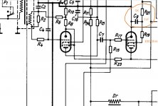
Klangfilm used in their famous V69 Cinema Amp just a 5K voltage drop resistor and 1uF from g2 to ground. Is that enough for buffering the screen grid, which is pigging out at approx 15-20mA? Why didnt they used a much bigger electrolytic cap for buffering I wonder. Why didnt they used a second resistor to ground to manage for negative current? Power tube is Siemens F2a. Sometimes easy things can look very complex.
Attachments
Last edited:
Don't want to "hijack" the thread but since I'm going to put a regulator (Maida type) on G2, the title took my attention...Is this the same thing for el84 types (7189, 6P14P)?
Thanks
Pierre
Thanks
Pierre
6L6 is supposed to be "aligned grid". G2 is wound in the shadow of G1. This is not as easy as it sounds. Ig2 on 6L6 varied some when RCA made them. Now that the machines have been sold around the world, and copied, G2 alignment may only be getting held "close enough".
5mA is not a problem.
The European Power Pentodes were real pigs for G2 current. RCA did it different, and I think they were proud to get it down to "nearly none" (on a good day); but it doesn't have to be real-small to work good.
Note also that under some conditions, a good 6L6's Ig2 can *reverse*. If you have a screen-only supply, it is wise to have a bleeder for 10%-20% of nominal Ig2, because simple supplies won't hold-down when current flows INto them.
I installed the basic Zener-Mosfet and I'm very happy with the results. First, I learned a few important things in the process which I wasn't aware of.
Different sets of my 6L6 tubes pull different screen current which made for a considerable variations of screen voltage. As I also found out, the plate current is very dependent on the screen voltage, which resulted in different operating points. With the regulator now in place, things are more stable.
As for sound improvements, not much at low listening levels, but I get an impression the bass and general imaging is better when played loud.
Crazyfrog: EL84 in Class A operation typically has Va=Vg2. If you intend to use a regulator, you must account for some voltage drop.
...EL84 in Class A operation typically has Va=Vg2.....
In General: common-sense (and low-cost) design results in Vg2 being very near Vp, for fewer parts and less heat.
This does require tubes made for Vg2 ~= Vp. A HIGH-current tube will be low Mu and want a low Vg2. TV sweep tubes, class C radio amps. However we have plenty of choice of "audio" tubes aimed for Vg2 near Vp.
------
Reverse Ig2 is, IIRC (it has been a while), due to secondary electrons from Plate landing on G2, in excess of the primary electrons to G2 (which aligned-grid tends to null). Now that you ask, the last time I saw this was a Metal 6L6.... it is possible that modern builds do not try so hard to eliminate primary G2 current so will not show this effect.
- Status
- This old topic is closed. If you want to reopen this topic, contact a moderator using the "Report Post" button.
- Home
- Amplifiers
- Tubes / Valves
- SE Pentode, regulated screen voltage?