That's 6 burning hot BJTs to spread out per channel.
Do keep in mind that Broskie publishes a lot of circuits that are visual aids in the articles he writes. These are often not necessarily fully developed or intended to be constructed, but you certainly won't know until you ask/try!
Do keep in mind that Broskie publishes a lot of circuits that are visual aids in the articles he writes. These are often not necessarily fully developed or intended to be constructed, but you certainly won't know until you ask/try!
You only need two of these:
SK 56/ 200 SA - FISCHER ELEKTRONIK - Heat Sink, Extruded, 0.3 C/W, 40 mm, 300 mm, 200 mm | Newark element14
300mm x 200mm isn't that big :/
SK 56/ 200 SA - FISCHER ELEKTRONIK - Heat Sink, Extruded, 0.3 C/W, 40 mm, 300 mm, 200 mm | Newark element14
300mm x 200mm isn't that big :/
Another alternative for 6L6GC

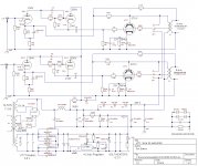
I found Mr. Ron schematic that use 6SL7 instead of 6SN7 with no need 12 bipolar
However it is KT77 which I need help to modify to suit with my stock tubes.
RSD 6L6GC.
Can anyone help adjust a little to get 4 watts Single Ended of 6L6GC?
Thank you very much.
Here is Mr. Ron link Thank you very much for sharing.
Ron's Audio KT77 SE Stereo Amplifier
Attachments
Last edited:
View attachment 645320
Can anyone help adjust a little to get 4 watts Single Ended of 6L6GC?
Ron's Audio KT77 SE Stereo Amplifier
I would change the 470 ohms Cathode resistor to 300 ohms. This should yield better linearity for a 6L6GC when it is switched to the Pentode mode. Also yield higher power output.
The input stage as post 10 mentioned has some limitation and also non-balanced. IMHO, I would have keep thing simple and use a standard common cathode design and save a tube. Or use the spare 1/2 tube to reduce power supply noise. Check diyaudioprojects, there are a number of good SE design there.
BTW: If you use this circuit, the 470 ohm bias resistor should somewhat work even if you just swap in a 6L6GC to a KT66 and change nothing.
With 0.6v on the bottom 6SL7 cathode, you'll quickly run into grid current problem. Not a good circuit, IMO.
This 0.6V is DC bias; thanks to negative feedback, it does not change much with input signal.
I like the circuit, it is good IMHO.
I have a couple questions re the schematic posted in #9. What is going on with R2, R4 and R5? R4 looks to be the plate resister for the 6SL7 w/the B+ sourced from the 6SL7 cathode. What are R2 and R5 doing. Looks like local feedback. Is that right? What about R1 and R3? R1 is standard global feedback. What is R3 doing? Local "Schade" type feedback in parallel w/global? If so, the 1.5M value is higher than I would have expected. Thanks for your enlightenment?
So to save cost can I do this?
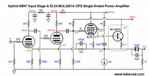
Not an optimal circuit. 6SN7 connected as differential amplifier has quite low gain. 18.3 dB without NFB from the cathode follower and 13.6 dB when local NFB is on.
This means that to get full ( ~4.5 W) output power, some 4.5 Vrms input signal is needed.
Also the supply voltage of 6SN7 is quite low taking into account that more than 60 Vpp drive voltage is required for 6L6.
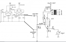
Local audio shop told me if you want to use 6SN7, You should do PP.
Here is the schematic he told me.
So I will go and buy more 6L6GC. It is very cheap tubes.
RSD 6L6GC sell only USD7.5 in my country. some are double D getter, some are single round getter at bottom.
Here is the schematic he told me.
So I will go and buy more 6L6GC. It is very cheap tubes.
RSD 6L6GC sell only USD7.5 in my country. some are double D getter, some are single round getter at bottom.
Last edited:
 The thread is closed as the OP is unable to stay on topic.
- Status
- Not open for further replies.
- Home
- Amplifiers
- Tubes / Valves
- SE Amp Options