Douk Audio 13W Class AB Amplifier - Advice Sought
Hi all. I have been wanting to build a tube amp for a very long time but never had the money or....well, just the money really.
I saw a push-pull kit, including chassis, on ebay for £150 and thought it was worth a try. I'm going to use it as the tweeter amp for my Linkwitz LX521s (and as a space heater, naturally). With import fees, it actually works out at closer to £230 but that could still prove to be very good value.
Anyway, it arrived in the post a week or so ago and I got around to unpacking it today. I think I'll do a little write up of the build as I go. Before I get started, I thought I'd post the schematics and ask whether anyone can see any easy improvements that could be made.
I know that the output transformers are probably the weak point here but, as I'm using it only to power tweeters, low frequency performance is irrelevant.
Though the schematics say ECC85 and EL84, the kit comes with 6N1 and 6P14 valves.
Attachments
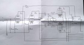
The 6P14’s should have their own cathode resistors and capacitors.
Where is the schematic ?
Where is the schematic ?
The links that say "Click the image to open in full size" are mis-linked. Instead, Right-click and Open In New Tab. (OP linked to the Imgur page, not the naked image.) The schematics are in there.
Oddly I do not see where to connect a speaker. (I do know where, but not drawn?)
As tweeter amps, the OT size is unimportant. While common cathode resistor allows significant unbalance, millions of amps worked this way OK. I would not be inclined to mess (much). If you are, feel free.
 Fixed linked images in the first post. To avoid dropped or missing images, please use the Forum's image attachment function, see How to attach images to your posts. for details.
So could someone just give a brief explanation of the pros/cons of a shared cathode resistor.
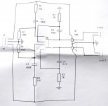
Also, I notice that many amps (such as the el-cheapo) use a constant current source for the phase splitter/input stage. Is that a worthwhile edition (or perhaps not, if the mains transformer doesn't include the right windings)?
Also, I notice that many amps (such as the el-cheapo) use a constant current source for the phase splitter/input stage. Is that a worthwhile edition (or perhaps not, if the mains transformer doesn't include the right windings)?
If the two output tubes are perfectly matched, then it does not matter. However, in practice seldom are the output tubes perfectly matched, therefore a shared cathode resistor means that both tubes are biased at the same voltage, even though their idle current are different. So for poorly matched tubes (e.g., due to aging), you could end up with one tube running 'cold' and the other 'hot', and in the worse case scenario, current hogging occurs which could destroy one of the tubes.
Having a CCS on the phase splitter ensures perfect phase balance, it's good to have but also requires a negative supply rail and some additional parts.
Having a CCS on the phase splitter ensures perfect phase balance, it's good to have but also requires a negative supply rail and some additional parts.
Put a 0.001 coupling cap between J1 pin 1 input and the 470k ohm grid resistor.
It will have a 338 Hz -3dB point, plenty low for any tweeter. (-1 dB at 677Hz).
It will prevent the bass frequencies from getting into the amp, and intermodulating with the tweeter frequencies.
That will help reduce any tube LF to HF intermodulation distortion, and especially any small output transformer to prevent Low Frequencies from intermodulating with the High Frequencies.
This is the proper way for optimum bi-amping.
Also, as previously stated, use 300 Ohm resistors per each output tube cathode bias.
But use 100uF bypass per each cathode, so that the negative feedback loop response is not affected.
If you use different output transformers, the negative feedback may need to be adjusted.
- Status
- This old topic is closed. If you want to reopen this topic, contact a moderator using the "Report Post" button.
- Home
- Amplifiers
- Tubes / Valves
- Cheap PP 6P14 Amplifier Kit