Just wanted to show off my daily driver. A Harman Kardon A300 dressed up in a dimestore EJ Korvette Mark IV skin. Modified to take 6L6 tubes and mostly driven by Pandora Jazz Four80East Radio. I really like the sound of this amp with the old school RCA and TUNG SOL 6L6GA coke bottle output tubes and the Baldwin preamp 12AX7's

Last edited:
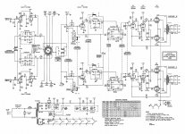
The HK A300 used the filaments of the two 12AX7 phono preamp tubes in series as the self bias resistor for all 4 output tubes (24V cathode self bias). This was how they got DC filaments for the phono stages.
The 6L6s plates may draw more B+ current than the original output tubes, and therefore the 12AX7 filaments will be running at more than 12V each.
And the 6L6 0.9A/filament may draw more current than the original output tubes (I can not remember what tube type the originals were).
I hope the power transformer does not get too hot.
I built the kit version of the HK A300; it was a very nice amp, but had a little noise from the filament to cathode leakage of the concertina phase invertors.
Just as I remembered, I thought the original output tubes were like a 6V6 (the 7408 is essentially a 6V6).
The filament current of the 6V6 and 7408 was 0.45A per output tube.
6L6s are 2 times the filament current.
It is time to check the DC Volts across the two 12AX7's filaments. 12.6 x 2 = 25.2 Volts. That would be 150mA, or 37.5mA for each of four 7408 cathodes (37.5mA plate + screen current per tube).
Last edited:
How can you change the 4 common cathodes circuit that runs the two Phono Preamp tubes?
You would need a 12V DC supply to run the two phono 12AX7 filaments in parallel.
And if you did that, I recommend 4 individual cathode resistors and 4 individual bypass caps for the output tubes.
12.6V x 2 = 25.2V. 25.2V/0.15A = 168 ohms. 4 x 168 = 672 Ohms.
You would need a 672 Ohm resistors for each cathode (25.2V / 37.5mA = 672 Ohms).
And you would also need 4 each 220uF 50V bypass capacitors.
That would allow a better match of the plate currents of the output tubes, and also the ability to see the bias voltage (and calculate the current) on each cathode, with the tubes new, and with them aged.
With individual cathode resistors, if one phono 12AX7 filament died (open), or if one of the phono 12AX7 tubes were pulled out of the socket, there would not be an over voltage on the output tube cathode bypass capacitors.
Last edited:
Those push pull output transformers are quite small. It is important to have Very Closely Matched plate currents of each channel (plate 1 of left channel to plate 2 of left channel; plate 1 of right channel to plate 2 of right channel).
push pull transformers do not have an air gap (single ended transformers do have an air gap).
Without an air gap and plate current matching, you will saturate the output transformers very early. And that will increase bass distortion, as well as the intermodulation of the bass onto the mid and high frequencies. Negative feedback will not be able to completely take care of this.
It does take more room, but you should be able to find room for 4 of todays modern electrolytic caps, and 4 cathode resistors, even if you have to mount the small electrolytics above the chassis. The 4 resistors will dissipate 1 watt each, so use those small 3 Watt wire wound resistors. 680 Ohms is a standard Ohmic value so use that.
"Matched" tubes are not always very well matched, especially at the voltage and current you will use them at, versus the test for matching. And as they age they may do so at different rates, becoming more unmatched.
Using 4 separate self bias circuits will allow the tubes to not have to be as perfectly matched.
Last edited:
The quickest way to modify (and see if you like it) is to install the 4 electrolytic caps, and the 4 cathode resistors. Then disconnect the phono 12AX7 filaments at the top end where they used to connect to the 4 cathodes (24.6V).
Now you can test the results as long as you use a non phono signal source (i.e. use a CD Player). Check the 4 individual cathode voltages.
If it all tests OK, and you like the results, then you can purchase and install the 12.6V DC filament supply for the Phono 12AX7.
Listen and enjoy.
Now you can test the results as long as you use a non phono signal source (i.e. use a CD Player). Check the 4 individual cathode voltages.
If it all tests OK, and you like the results, then you can purchase and install the 12.6V DC filament supply for the Phono 12AX7.
Listen and enjoy.
The original circuit was all 4 cathodes current passing through the series filaments of the two 12AX7 preamp tubes. 25.2V / 0.15Amp = 168 Ohms.
0.15 Amp / 4 tubes = 37.5 mA per cathode.
168 Ohms x 4 = 672 Ohms.
We will use four each 680 Ohm 3 watt wire wound resistors, preferably 1%.
Each cathode's current should now pass through the 'parallel combination of 680 Ohms and 220uF' to ground. That is 4 individual cathode circuits of 680 Ohms, and each individual resistor is bypassed with its own capacitor.
25.2V cathode bias / 680 Ohms = 0.037 Amps = 37 mA
Take the tubes in the Left channel:
If one tube has 26V and 680 Ohms, the current is 38.2 mA
If the other tube has 24V and 680 Ohms, the current is 35.29 mA
The difference current in the Left channel output transformer primary is 38.2 - 35.29 = 2.91 mA. Hopefully, you will have a better current balance than this. But now you can test all 4 tubes.
Put the two with the lowest current on one channel, and put the two with the highest current on the other channel.
Then decide if you want to purchase matched pairs of tubes (from those who will reliably
match the tubes at or near the voltage and current you will use them at).
I have a couple of vendors that have matched new production tubes for me, and I did not even tell them what voltage and current to match them at. But because of my circuits that used self bias, and that do not push the tubes to their limits, they matched very well (usually at 500uA or less difference).
I hope that explains it.
- Status
- This old topic is closed. If you want to reopen this topic, contact a moderator using the "Report Post" button.
- Home
- Amplifiers
- Tubes / Valves
- XAM Stereophonic High Fidelity