The Cheating 80 Watt Spud Amp
Use a 42/6KN6 tube (the older version with two internal tube sections) and self split that with a hidden Mosfet over a CCS tail into a conventional P-P OT. Maybe 40 Watts output in class A. Since it LOOKS like a dual pentode, bring TWO wires down from the plate cap and let them plug into separate banana jacks on the chassis. With a step-up input xfmr, could drive both grid and gate for twice the gain and P-P sonics (and twice the Watts out in class aB, no CCS tail then).
Use a 42/6KN6 tube (the older version with two internal tube sections) and self split that with a hidden Mosfet over a CCS tail into a conventional P-P OT. Maybe 40 Watts output in class A. Since it LOOKS like a dual pentode, bring TWO wires down from the plate cap and let them plug into separate banana jacks on the chassis. With a step-up input xfmr, could drive both grid and gate for twice the gain and P-P sonics (and twice the Watts out in class aB, no CCS tail then).
Attachments
Last edited:
Oh, I wanted you to enlighten us how this could make a PP, but then you edited it with "cheating" title, yeah WTH to bother with this one while there a better obtainable one - 6S33S. And why not make 4 wires to chassis so it works as a stereo-SPUD? Also, with this one the additional control can be introduced: a half filament / half power switch.
Lets see: 832A or 815A for two plate caps SPUD.
Or 701A or 304TL/TH for cheating 500 Watt STEREO SPUD. 4 plate cap wires (+ 3 Big Mosfets on back heatsink) (or 4 Mosfets for the multiplex case below)
With some Mosfet switching, one could RF multplex the tube through 2 or 4 tube positions on the P-P OT(s) (put 2 Mosfet switches under the cathode (stereo dual OT case), use dual primary OTs with Mosfet B+ switches ( for P-P phase position control).
Then RF LP filter the output at the OT primary.
2 or 4 plate cap wires would be a good idea then for low RF loss.
Or 701A or 304TL/TH for cheating 500 Watt STEREO SPUD. 4 plate cap wires (+ 3 Big Mosfets on back heatsink) (or 4 Mosfets for the multiplex case below)
I wanted you to enlighten us how this could make a PP
With some Mosfet switching, one could RF multplex the tube through 2 or 4 tube positions on the P-P OT(s) (put 2 Mosfet switches under the cathode (stereo dual OT case), use dual primary OTs with Mosfet B+ switches ( for P-P phase position control).
Then RF LP filter the output at the OT primary.
2 or 4 plate cap wires would be a good idea then for low RF loss.
Attachments
Last edited:
A more practical multiplexing design:
To avoid B+ high side switching of the two primary sides (needing un-obtanium HV P Channel Mosfets), use separate B+ supplies for each phase side of the OT(s). Then low side switch (to ground) the negative terminals of the two B+ supplies. All N Channel Mosfets used then, even for stereo case (HV N type Mosfet models available). 2 x B+ minimum ratings.
To avoid B+ high side switching of the two primary sides (needing un-obtanium HV P Channel Mosfets), use separate B+ supplies for each phase side of the OT(s). Then low side switch (to ground) the negative terminals of the two B+ supplies. All N Channel Mosfets used then, even for stereo case (HV N type Mosfet models available). 2 x B+ minimum ratings.
Multiplexing the B+ supplies:
Low capacitance multi bobbin HV xfmr(s) needed then, since the two B+ supplies will be flying around at RF. Could then resonate the residual distributed capacitance out, for a tuned RF multiplex scheme. (single frequency sine wave RF instead of square wave multiplexing)
Better: No multiplexing the B+ supply:
Or could avoid the flying B+ issue by putting the (N channel) Mosfet multiplexers at the plate (to the two OT primary phases), using two RF gate drive ferrite xfmrs. This is probably the best way. Only one stationary B+ supply needed then, even for stereo. And the OT's can be conventional P-P with CT'd primary.
Last edited:
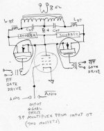
Here we go, a rough schematic for a single channel multiplexed SPUD AMP, using a single element type tube (like 42KN6).
Typo edit on schematic, should be: Input signal RF Multiplex from input xfmr. (two Mosfets from the phase splitter or input xfmr)
Typo edit on schematic, should be: Input signal RF Multiplex from input xfmr. (two Mosfets from the phase splitter or input xfmr)
Attachments
Last edited:
Here we go, a rough schematic for a single channel multiplexed SPUD AMP, using a single element type tube (like 42KN6).
[Typo edit on schematic: Input signal RF Multiplex from input xfmr. ] (not OT)
You can also get to Chicago from NYC by going east.
You can also get to Chicago from NYC by going east.
Going to be hard to get 500 Watts from a dual pentode like 6BN11. (or even 80 Watts)
If your plane flies Mach 10, who cares which way you go.
Going to be hard to get 500 Watts from a dual pentode like 6BN11. (or even 80 Watts)
If your plane flies Mach 10, who cares which way you go.
Since there seems to be no rules on the design, then let's just use a 12AU7 to drive some 500W OTL SS outputs. SPUD!
Since there seems to be no rules on the design
Well, I think the tube should look -almost- believable for for the specified max output power. But not quite.... 10 Watts out would be max acceptable for 12AU7. It should leave the reviewer in some awe as to how the design was accomplished, but not total dis-belief. The total amplifier should also not be disproportionately big either for the tube used.
This is just the mirror reflection of those odd pre-amps using huge tubes to get milli-Watts output. Maybe they should be used together.
Then there are those two tube Matrix amps that use P-P differential and SE common mode together to get two audio channels. Shouldn't those qualify as stereo SPUD amps? One would not face the problem of finding dual pentodes of reasonable size there. Two 42KN6 (doublets) would fit right in cosmetically.
For example:
The Matrix Amplifier
And finally, there are the Beam Deflection Tubes (BDT) that can perform as P-P outputs (about 1 Watt max). Putting some Mosfet HV cascodes above a BDT would allow higher power output. That would even work for the 6BN11 if you use 1 KV B+.
.
Last edited:
And finally, there are the Beam Deflection Tubes (BDT) that can perform as P-P outputs (about 1 Watt max). Putting some Mosfet HV cascodes above a BDT would allow higher power output. That would even work for the 6BN11 if you use 1 KV B+.
My DVD player puts out 2v RMS. That would drive a 6BQ5 directly via a VC and coupling cap. You might not get the last 4 dB of power on a 7v bias but....
42KN6 gives you 16000 gm at 100 mA.
E130L/7534 gives you 25000 gm at 100 mA,
and E55L/8233 gives you 45000 gm at 50 mA
All are single pentodes.
If you are going to use two tubes in a Matrix stereo amp, then two: 6LY8, 6KR8, 6HZ8, 8AL9, 6AH9, 6AG9, 6LU8, 6LR8, 6KY8, 6MF8, 6JZ8 ...
would provide decent pentode output tubes and voltage gain triodes.
Then there are all the dual dissimilar Vertical Amp triodes.
Last edited:
If there was something like a dual sweep tube or something similar...then we're talking.
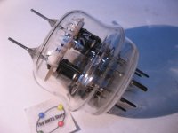
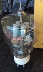
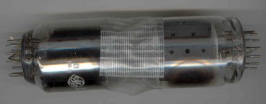
Introducing the new Raytheon double ended 6HJ5 (use a Teflon sleeve!)
Features a 12 pin plate cap with two 24 Watt beam pentodes inside.
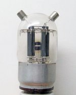
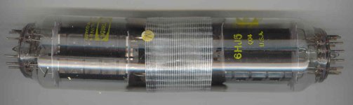
And the new GE double ended 12GE5. (pre-production model)
Attachments
Last edited:
Maybe 40 Watts output in class A
Since the tube in question is operating single ended, it must run class A. 40 watts? Maybe in the meltdown region, which is somewhere beyond the red zone. Those old twin tube 6KN6's really like to red plate in the area where the plates face each other.
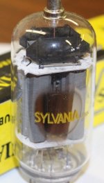
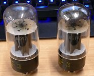
So we are taping tubes together. Why, when the tube makers have already put a pair of pentode audio output tubes together in a single octal bottle for you. Not once, but twice. The Sylvania 6DY7 will give you 20 watts from a single bottle. The GE 6DZ7 is rated for 18 watts of audio output from a single tube. Both are rather scarce today though. I found my 6DY7's. Don't know where the 6DZ7 is, or if any of these are good. One looks kinda toasty.
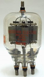
The 815 is probably the best choice for a realistic single tube push pull amp. It is a pair of 2E26's in a single bottle and I have seen one crank out over 60 watts, but I might have bent a rating or three. It wasn't glowing and no fakery is needed.
The RCA published data shows 54 watts of audio from a pair of 2E26's in AB2, but driving power is needed for AB2. I don't know how much power you can get in AB1, or if you can get there with a low impedance driving source and a suitable transformer.
Attachments
I just got back online after the big storm/tornado nearly wiped out Hickory yesterday.
Phone still not working. From 40,000 out of service last night, I got power back when it got down to 250 out of service this afternoon. Guess I'm not a real priority!
The 80 Watt 6KN6 idea was for using a hidden heatsinked Mosfet for the other P-P side in class aB. And 40 Watts was for a self splitting, class A, P-P using the hidden Mosfet. Hence the "Cheating" SPUD title. (post #1) Just rough guesses on the power capability. I don't even have a 42/6KN6 tube.
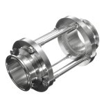
How about if I put two TV Sweep tubes in an evacuated "bottle" with feed-thru's, like below. Does that count as a SPUD tube?
Phone still not working. From 40,000 out of service last night, I got power back when it got down to 250 out of service this afternoon. Guess I'm not a real priority!
The 80 Watt 6KN6 idea was for using a hidden heatsinked Mosfet for the other P-P side in class aB. And 40 Watts was for a self splitting, class A, P-P using the hidden Mosfet. Hence the "Cheating" SPUD title. (post #1) Just rough guesses on the power capability. I don't even have a 42/6KN6 tube.
How about if I put two TV Sweep tubes in an evacuated "bottle" with feed-thru's, like below. Does that count as a SPUD tube?
Attachments
Whoa... I've got it now.
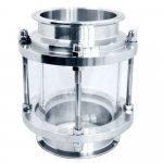
Put one big tube up front with a big glass window behind it. Then put the second identical (P-P) tube behind the glass so it looks like a reflection of that in a mirror. Could put in some other chassis top components, both in front of and behind the glass window, to reinforce the "mirror" mirage. Call it the "Mirage" SPUD amplifier. (or Smoke and Mirrors?) Would be especially interesting if the window could be toggle switch flipped between transparent and mirror effect by some electro-sensitive surface effect.
One could even mount the "mirror" tube on a half turntable base affixed to the back of the glass. So rotating the "mirror" small angles would cause the "image" to rotate around behind as expected.
And to see if the observer is paying close attention, use 2 plate cap wires on the front 42KN6 tube, and three wires on the "mirror image" tube.
Last edited:
. .. put two TV Sweep tubes in an evacuated "bottle" with feed-thru's, like below. Does that count as a SPUD tube?
Giz, these are good for silicone up-sized-super-dampers!
- Status
- This old topic is closed. If you want to reopen this topic, contact a moderator using the "Report Post" button.
- Home
- Amplifiers
- Tubes / Valves
- The Cheating 80 Watt Spud Amp