One good cheat deserves another.
It seems silly to require an input xfmr to avoid gain tubes for these SPUD amplifiers. So the next feature I'm adding is an "IC" front end, but not like any IC you have ever seen before. No, this will be a black metal case shaped like a DIP package, but much bigger. Two rows of "pins" along the sides will allow it to plug into the chassis like a DIP package ( right angle header pins and chassis receptacles).
On the top of the "IC" will be either a clear window with 4 horizontal sub-mini tubes visible inside, or a row of round AUGAT Teflon IC sockets on top with 4 sub-mini tubes vertically plugged in. Maybe two 5744 triodes (differential front end/phase splitter) and two 5639 pentodes (differential video drivers). Thus an IC front end made with tubes. Only one "IC" per channel of course, in keeping with the SPUD theme.
This then driving the "mirrored" Output tube(s). Maybe use a half silvered mirror behind the front visible output tube, with the other (P-P) output tube semi-hidden behind the partial mirror (positioned to match the reflection of the visible tube) 42KN6 (double section) output tubes of course, with double wired plate caps. What is real, what is not.
The Smoke and Mirrors Amplifier.
..
Last edited:
I think you are close to get banned for such the heresy. DIP package, huh?!
I agree that the oxygen-free speaker cables are laughable, but messing up with teflon tube bases and, especially, with sacred balanced spud front stage attracts all kinds of curses on your soul. .. each time someone says one makes you flip around in your bed (and further in coffin), and I bet if you do not stop right now you will be spinning like a ceiling fan at hot Mexican noon.
I agree that the oxygen-free speaker cables are laughable, but messing up with teflon tube bases and, especially, with sacred balanced spud front stage attracts all kinds of curses on your soul. .. each time someone says one makes you flip around in your bed (and further in coffin), and I bet if you do not stop right now you will be spinning like a ceiling fan at hot Mexican noon.
Last edited:
It gives the -illusion- of being a SPUD Amp, but is anything but.
OK, I get it. take one 833A light it up and make it glow, maybe two for the stereo effect.......
Hide one TI TPA3255 evaluation board (300 WPC Class D) inside a SMPS chassis along with a suitable SMPS, make it look cool and.....done. Meet your criteria?
Attachments
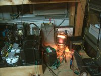
Real Spud, 5 to 10 WPC. Take one of those "useless" beam triodes for TV HV regulator like a 6HV5, 6HZ5, 6JD5, or 6HS5, connect a power supply and OPT in the usual manner, ground the cathode and drive the grid directly with a source that has a resistance to ground (or add a parallel resistor). I used the headphone output of a Sony Discman portable CD player. Crank the B+ up until the desired plate current is reached.
Note that these tubes have a Gm in the 50,000 to 65,000 range and a Mu of 300 so not much drive is needed. You can't build a simpler amp and it works........
Drawbacks? Some driving power is needed since the tube is operating with zero bias. These tubes need voltage. The plate voltage required to get 50 mA of tube current? About 650 volts. I found that this voltage can be decreased by tying the beam plates to the plate instead of the cathode, but the clip lead furball kept breaking into oscillation. Bass was rather loose since the Rp of these tubes is high.
No further experiments were done.
Take one of those "useless" beam triodes for TV HV regulator like a 6HV5, 6HZ5, 6JD5, or 6HS5,
Thanks for the temptation George.
1. One PP pair per channel of this useless triodes with B+ around 600V
2. Drive with DC coupled op-amp splitter at zero bias
3. Use rather steep loadline with Zaa 4k OPT
Easy 125-150WPC class AB2 (550V peak plate swing at 550mA peak current). Tell me how this is not a good idea?

Hide one TI TPA3255 evaluation board (300 WPC Class D) inside
I think it would be reasonable to require the tube(s) displayed to be doing the actual amplification. Notice that my design above uses NO SS components in reality. Hiding the 2nd P-P tube was the trick there. The tube "IC" could just as well be in a preamp chassis, or a Philbrick OP Amp case.
Hmmm, maybe put each of the sub-mini tubes in a hollowed out clear crystal, with wires attached, like the original Bell Labs transister.
A glowing crystal ball!
Time to visit the lamp fixtures dept. at Lowes Hardw. And one or two of those old Xmas tree bulb bubblers inside too, with LED illumination. Busy things going on inside from the shadows moving around in it.
-------
6HV5A 550ma!
http://tubedata.milbert.com/sheets/123/6/6HV5A.pdf
325 mA peak, 35 Watt diss.
Everyone thinks those Beam Triodes are just the thing until they actually try one. Can't even get a decent curve trace for them on the curve tracer. Positive grid, Class A2+, might get the current up some, but these have frame grids. Pooooff!
Last edited:
Peak plate current is only 300-325mA
The physical size of the internals dictate a much higher real current capability.
History with close spaced grids in high powered audio tubes like the 8417 was not so good. Flakes of cathode material dislodged due to high peak currents caused cathode to control grid shorts.
These pulse regulators have an "improved diffusion bonded cathode" to prevent these issues, which might be the real reason for the low peak current rating. I got a dozen or so of these when they were on the dollar list, plus several more from hamfests but oscillation issues never let me test at high power levels.
but these have frame grids. Pooooff!
With a Mu of 300 you don't need much positive voltage.
- Status
- This old topic is closed. If you want to reopen this topic, contact a moderator using the "Report Post" button.
- Home
- Amplifiers
- Tubes / Valves
- The Cheating 80 Watt Spud Amp