Hi All,
I am for the first time designing a small push pull audio output stage based on a pair of 6J6 triodes (each common cathode triode in parallel). Having only designed Pentode PP stages I noticed now that on the triode load lines there is no Wa / Pd max power dissipation curve... why is this?
And can this be manually calculated and drawn onto the existing curves easily?
Apologies if it is a silly question but I have to ask.
Cheers,
Matt.
If you're doing all this by hand, you can add a couple of points onto the curves and just fudge the actual curve. In practice, you won't generally be up against that limit too hard.
How many 6J6s do you plan to use per channel? I have tons of these things sitting in a bin somewhere.
How many 6J6s do you plan to use per channel? I have tons of these things sitting in a bin somewhere.
Thanks for the replies. Very helpful.
Plan to use 4 6J6 per channel in push pull giving a theoretical Pmax of 12w per channel. The twin triodes are capable of 1.5w max each, so 3w per envelope in parallel. Actual power will be around 9-10wrms I believe.
They are my favourite valve because they are cheap and cheerful, though a bit microphonic. My first triode push pull project so very interesting!
To answer your question, why the data has no anode dissipation limit curve:-
The 6J6 was intended to be a small signal RF twin triode. In this service the signal excursion voltage at the anode is negligible compared to the static HT. And unless the designer had special reasons, he used the 6J6 at the "typical operating conditions"/recommended anode voltage and current.
Of course an electronic engineer can very smartly plot a curve if he wants, just as cozido said.
None of means that it should not be used for audio or audio output - RF triodes make very good audio tubes.
Keit
No, 1.5W is the max anode dissipation, not the output power.Thanks for the replies. Very helpful.
Plan to use 4 6J6 per channel in push pull giving a theoretical Pmax of 12w per channel. The twin triodes are capable of 1.5w max each, so 3w per envelope in parallel. Actual power will be around 9-10w rms I believe.
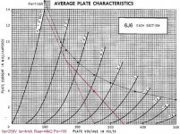
With 250V and one tube in PP you get 1W out (Raa=44kΩ)
If you use 4 tubes in one PP stage with Raa=11kΩ that gives 4W out.
Mona
Attachments
Yeah, I would run at least eight tubes per channel to get the load impedance down to a reasonable level. You could run another pair per channel as cathode followers to drive the miller capacitance of the output tubes, then another behind that as a LTP, and one more behind with sections paralleled as a voltage amp.
So 12 6J6 per channel, a 6K push-pull OT. Lots of little holes in the chassis!
So 12 6J6 per channel, a 6K push-pull OT. Lots of little holes in the chassis!
Yeah, I would run at least eight tubes per channel to get the load impedance down to a reasonable level. You could run another pair per channel as cathode followers to drive the miller capacitance of the output tubes, .......
Yes, indeed. Cgp one triode is 3.8 pF, amplification factor 38, so 8 pairs of triodes = about 1.1 nF of Miller each side of the push-pull stage. For 20Khz cutoff, the driver output impedance cannot exceed 7 kohm. Those cathode follower drivers are needed!
Keit
See page 33:And can this be manually calculated and drawn onto the existing curves easily?
http://valvewizard.co.uk/Common_Gain_Stage.pdf
6J6 can be worked two ways.
No grid current. I trust Ketje's plot to guide you here.
WITH grid current. 6J6 was used as a small UHF power transmitter in an early radar-like system. You can get a "lot" more peak plate current by pushing the grid positive. In audio, the problem is that the grid impedance falls radically from many-Megs for small signals to under 1K for very large signals. You can not use R-C coupling, bias will shift. Your driver distorts, no reasonable driver tube can manage the large jump to a low impedance. You "can" use something like another 6J6 into 10KCT:600CT to get a better grid match. However if you run too far up the positive grid zone, the Power Gain falls to hardly-any; your driver is bigger than your output.
I think this is costly way to get some Watts. Both in labor and in heater transformers. But if you are over-supplied with 6J6es, labor, and iron, well, there's worse ways to spend your days.
Nah, you'd be silly to be committed to running so many 6V tubes on 6V. One just needs to figure out how to use 19 or 20 of these in this arrangement, then a 500mA isolation transformer can be used to heat them up. (and another such transformer might work OK for B+ duties too)
Be careful when running a series string of 6J6 filaments. The rating for Peak voltage from the filament to the cathode is +/-100V (200V peak to peak, centered about ground).
That maximum rating goes for DC, AC, and DC + AC.
Even the 100Vrms mains of Japan is +/- 141.4V peak. An isolation transformer will not work for a string of 6J6s, unless it steps down the voltage to 70Vrms or less.
Each 6J6 should have it's own bias, i.e. cathode resistor and bypass cap, or individually adjustable "fixed" grid bias voltage (with some way to sense the current). Parallel tubes require careful handling in order to get good sounding results, and to lengthen tube longevity. And that requires lots of work and parts.
I prefer to use the 6J6 to drive the amplifier output tube(s):
Use individual grid stoppers, this is an RF tube.
For push pull amplifiers use as a cathode coupled phase inverter with a current source in the cathode (the cathode is already common).
For use as a driver in single ended amplifiers, use self biased/cap bypassed cathode (one cathode is already common to the 2 triodes), either use as a stereo driver (L, R), or Mono Block: parallel the 2 grids (individual grid stoppers) and parallel the 2 plates. Use current source(s) in the plate(s). Better linearity and more gain with current sources.
Also, a triode with cathode self bias and a current source in the plate works predictably.
With proper design, you can drive these tubes: 45, 2A3, 300B, and pentodes/beam power tubes that are connected as triode wired: EL84, 7591, KT77, KT66, 807, EL34, 6L6, KT88, etc., and not have to use any negative feedback.
Use a 100 Ohm resistor from the plate to the screen grid of the pentodes/beam power tubes.
For any amplifier with an output tube that has a very high cathode to grid bias voltage,
always check to see if the driver tube can swing that far (and can do so with good linearity).
I know, that moves us away from the all 6J6 amp that you originally intended.
Do build the 6J6s amp first, and enjoy.
Then you might later decide to build using one of the above output tubes and a 6J6 driver in another amp.
- Status
- This old topic is closed. If you want to reopen this topic, contact a moderator using the "Report Post" button.
- Home
- Amplifiers
- Tubes / Valves
- Wa / Pd Power dissipation load line curve for Triodes?