Turn your phone off and try again.
Ha - good thought but I tried that.
Does your amp have a RF filter on the front end ?
It will be a resistor in series with signal followed by a capacitor to ground.
One of my early designs didn't have this and picked up local police radio crystal clear !
Without those components the front end of the amp demodulates RF.
It will be a resistor in series with signal followed by a capacitor to ground.
One of my early designs didn't have this and picked up local police radio crystal clear !
Without those components the front end of the amp demodulates RF.
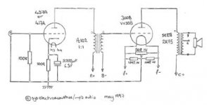
The input valve (5842) is particularly susceptible to picking up RF I know. I use the "cone of silence" method, 500R on each of the 4 grid pins, which join at the top and the input signal comes in there. The cone of silence acts with the miller capacitance from the valve to filter out high frequencies. The input is SE at the 5842 grid, having been converted from balanced by input transformer.
I don't have a schematic handy for the signal, but it's based on this from SJS (thanks Simon). The key differences are;
- cone of silence arrangement on the grids as described above
- 73K input load
- 60R and 80R cathode resistor options (I've tried both with no effect on the motorboating)
- 45 instead of 300B
I need to pin down exactly where the noise is being caused. I have an old analog oscilloscope which I've never used - maybe it's time to learn.
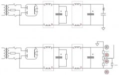
I've also attached the PSU schematic. 3 fully independent rails, 2 positive (5842 and 45) follow the upper diagram, 1 negative for bias follows the lower.
I don't have a schematic handy for the signal, but it's based on this from SJS (thanks Simon). The key differences are;
- cone of silence arrangement on the grids as described above
- 73K input load
- 60R and 80R cathode resistor options (I've tried both with no effect on the motorboating)
- 45 instead of 300B
I need to pin down exactly where the noise is being caused. I have an old analog oscilloscope which I've never used - maybe it's time to learn.
I've also attached the PSU schematic. 3 fully independent rails, 2 positive (5842 and 45) follow the upper diagram, 1 negative for bias follows the lower.
Attachments
Last edited:
Picking up one of Wavebourne's old posts I just tried a 50pF cap across the 73k load resistor, but to no effect.
I've tried cleaning the valve pins and in fact have swapped out to known good valves. All the bases are new.
I think I need help in how to pin down exactly where it is being caused. All tips welcomed.
I've tried cleaning the valve pins and in fact have swapped out to known good valves. All the bases are new.
I think I need help in how to pin down exactly where it is being caused. All tips welcomed.
Voice 002_sd.wav - Google Drive
I uploaded a WAV of the sound to the link above. It was recorded with my phone a few inches from the speaker. The noise does not change with the proximity of the phone.
I uploaded a WAV of the sound to the link above. It was recorded with my phone a few inches from the speaker. The noise does not change with the proximity of the phone.
This sound reminds me what I hear when I put my DAF96 preamp too close to the CD player. It does pick up electromagnetic interference from the CD player servo. I use a 10M grid resistor, so the grid impedence is very high. Have you tried to move the amplifier in a different position?
Short the inputs, test again. Put a 1R resistor across the secondary of the interstage transformer and test again.
The scope is a good idea.
You can also run an amp like that with no 5842 (or a resistor in its place to put some standing current on your interstage transformer) to see if the noise is coming from the output stage.
The scope is a good idea.
You can also run an amp like that with no 5842 (or a resistor in its place to put some standing current on your interstage transformer) to see if the noise is coming from the output stage.
BTW, the credit for the phrase "cone of silence" goes to beancounter in this thread
Purpose of 5842 tube?!?
I like Valve Wizard's pages, and this one on grid stoppers is quite clear.
The Valve Wizard
The data sheet for the 5842 has Cgk = 9pF and Cga = 1.8pF. Estimate interpin capacitance as 1.5pF and amplification factor as 40 and we get
Cin = 10.5 + 40 * 3.3 = 142.5 ... about 150pF
For a low-pass filter with -3db at, say, 20KHz I need a grid stopper of about 53k ! 4 x 500R is 125R, completely wrong, where did I get that from ?
I'll increase the value of that grid stopper, initially by adding a 50k at the cone junction. If that works I'll experiment with values. From the above thread, Johnson noise is only a concern if there is current flow, but I'd still prefer not to overdo it.
Last edited:
Cone vs No-Cone ?
Just thinking about the "Cone of Silence". My prototype amp didn't have the cone nor even a grid stopper and it sounded great. However the latest build included it and sounded fantastic - the improvement due to a whole host of other changes, not the cone I don't think.
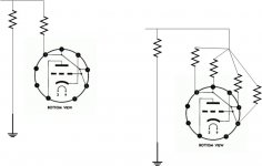
My point is that I'm having doubts about whether it's best to connect simply to 1 of the 4 grid pins or to use the cone.
Simple diagram attached - since the 4 grid pins are connected inside the valve, doesn't connecting the pins together just make a bigger loop aerial ?
I guess the answer is to try both and listen.
Just thinking about the "Cone of Silence". My prototype amp didn't have the cone nor even a grid stopper and it sounded great. However the latest build included it and sounded fantastic - the improvement due to a whole host of other changes, not the cone I don't think.
My point is that I'm having doubts about whether it's best to connect simply to 1 of the 4 grid pins or to use the cone.
Simple diagram attached - since the 4 grid pins are connected inside the valve, doesn't connecting the pins together just make a bigger loop aerial ?
I guess the answer is to try both and listen.
Attachments
BTW, the credit for the phrase "cone of silence" goes to beancounter in this thread
Purpose of 5842 tube?!?
I like Valve Wizard's pages, and this one on grid stoppers is quite clear.
The Valve Wizard
The data sheet for the 5842 has Cgk = 9pF and Cga = 1.8pF. Estimate interpin capacitance as 1.5pF and amplification factor as 40 and we get
Cin = 10.5 + 40 * 3.3 = 142.5 ... about 150pF
For a low-pass filter with -3db at, say, 20KHz I need a grid stopper of about 53k ! 4 x 500R is 125R, completely wrong, where did I get that from ?
I'll increase the value of that grid stopper, initially by adding a 50k at the cone junction. If that works I'll experiment with values. From the above thread, Johnson noise is only a concern if there is current flow, but I'd still prefer not to overdo it.
Actually with 4 grid pins, do we have 4 times the total Cin ?
By using the cone of silence, do we effectively filter each grid pin rather than the whole ?
SINGLE-GRID-PIN
Cin = 4 x (Cgk + 1.5) + 4 x 40 x (Cak + 1.5) = about 570pF
For 20KHz, use 14K grid stop
CONE
Each grid Cin = 150pF
For 20KHz filter on each grid pin, use 53K grid stop
I'm probably overthinking this, but I'd love to understand this better.
I'd also mention that often times when you have oscillations present, your voltages will be off from what you expected. Having the IT sitting between the power supply and plate means that you aren't going to see a weird plate voltage, but your cathode voltage may not quite be what you expect.
Hmmm I hadn't considered that. I have 2 cathode resistors in place (60R and 80R) to allow me to easily switch between them (by soldering, not by a switch). I'd been taking it as read that V / R = mA. I'll look again at those measurements, thanks.
Thinking further on that, yes I had been surprised that in tuning the dropper resistor and cathode resistor I hadn't been getting the mA I was expecting. That's a useful comment and thanks.
Thinking further on that, yes I had been surprised that in tuning the dropper resistor and cathode resistor I hadn't been getting the mA I was expecting. That's a useful comment and thanks.
Last edited:
- Status
- This old topic is closed. If you want to reopen this topic, contact a moderator using the "Report Post" button.
- Home
- Amplifiers
- Tubes / Valves
- Help diagnosing weird noise