View attachment 641341
Hey everyone. I'm just wondering if I'm right on this.
The 6L6 datasheet lists a 6k6 load for fixed bias, and a 9k load for cathode bias, however I'm using CCS for the cathode, not a resistor. I've heard this lowers Zo compared to a resistor bypassed with a cap. Is this true?
As it is the circuit will run with a 5k load (the transformer I'm using).
At this load should I just run it in triode and accept the lower Po or will beam tetrode mode with regulated screens work satisfactorily at this OP?
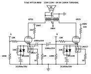
380V B+ for plate, 280V screen, 360V cathode to plate.
Thanks!
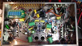
Here's a picture of the work so far. It's an integrated amp with a buffer, headphone amp, line amp, phono amp, and a 6P3S/6N9S output based on the old Acrosound 6L6. It features relay switched inputs, a relay based DACT, 9 inputs, tube level meters based on 6E2, and a IN12B nixie to display which input it's set to. Separate power supply based on an ATX computer supply feeding two switching boost modules for B+
Also Mica vs silicon pad for the LM317?
* mistake on schematic! 1000u 50V, not 25V
The 6L6 datasheet lists a 6k6 load for fixed bias, and a 9k load for cathode bias, however I'm using CCS for the cathode, not a resistor. I've heard this lowers Zo compared to a resistor bypassed with a cap. Is this true?
As it is the circuit will run with a 5k load (the transformer I'm using).
At this load should I just run it in triode and accept the lower Po or will beam tetrode mode with regulated screens work satisfactorily at this OP?
380V B+ for plate, 280V screen, 360V cathode to plate.
Thanks!
Here's a picture of the work so far. It's an integrated amp with a buffer, headphone amp, line amp, phono amp, and a 6P3S/6N9S output based on the old Acrosound 6L6. It features relay switched inputs, a relay based DACT, 9 inputs, tube level meters based on 6E2, and a IN12B nixie to display which input it's set to. Separate power supply based on an ATX computer supply feeding two switching boost modules for B+
Also Mica vs silicon pad for the LM317?
* mistake on schematic! 1000u 50V, not 25V
Attachments
Last edited:
.....I've heard this lowers Zo compared to a resistor bypassed with a cap......
No. But if I am understanding your choices, BOTH look into a Big Cap for audio. R or CCS makes no difference.
AND...... the rp of a 6L6 or any power tetr/pentode is MUCH higher than the good-output load resistance.
In an SE stage, the "happy load" for Pentode is roughly V/I.
But V*I must be some less or = to max plate dissipation.
Push-pull gets a little trickier, but not far different when you account for transformer ratio.
So you select your load for the voltage, current, and power which is convenient. Or if you have an OT in hand, you pick voltage to suit.
Last edited:
View attachment 641341 Hey everyone. I'm just wondering if I'm right on this.
The 6L6 datasheet lists a 6k6 load for fixed bias, and a 9k load for cathode bias, however I'm using CCS for the cathode, not a resistor. I've heard this lowers Zo compared to a resistor bypassed with a cap. Is this true?
These are the wrong data. This is for Class AB1. Since you're using CCSs in the tails of the finals, this enforces Class A conditions.
As it is the circuit will run with a 5k load (the transformer I'm using).
At this load should I just run it in triode and accept the lower Po or will beam tetrode mode with regulated screens work satisfactorily at this OP?
380V B+ for plate, 280V screen, 360V cathode to plate.
The spec sheet for the 6L6 recommends a load of 5K (P-2-P) for Class A PP, so you're good to go with that OPT.
These are the wrong data. This is for Class AB1. Since you're using CCSs in the tails of the finals, this enforces Class A conditions.
The spec sheet for the 6L6 recommends a load of 5K (P-2-P) for Class A PP, so you're good to go with that OPT.
Actually it's not strictly class A...
From Broskie RE this CCS scheme: Cathode Bias with a Counstant Current Source
"if we never increase the volume beyond the class-A limit, the constant-current source is only being shunted by a 10k resistor, which can be safely ignored. On the other hand, if the crescendo takes an output tube outside the class-A envelope, the rightmost diode will begin conducting and effectively couple the capacitor to the cathodes, which will greatly limit their AC movement away from the established DC bias voltage. Of course, if the increased volume is sustained for long enough, the capacitor will charge up to a much higher voltage. But once the volume falls to normal, the leftmost diode will begin conducting, allowing the capacitor to discharge through the constant-current source.
It's not perfect, but it would allow a two-speed operation to the amplifier. In other words, instead of having a class-A amplifier that puts out only 25W, we could have class-A amplifier that puts out nominally only 25W, but could be overdriven to produce clean 50W (or more) bursts of power."
- Status
- This old topic is closed. If you want to reopen this topic, contact a moderator using the "Report Post" button.