Hi guys.
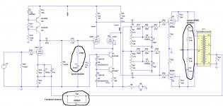
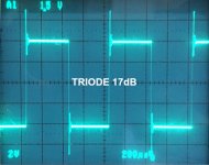
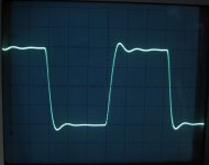
Just put in compensation networks for feedback for my 6550 push-pull amplifier. A rough schematic is shown with the simple compensation networks circled. There is 17dB feedback. I didn't use the feedback network circled at the transformer. The uncompensated square wave response is attached.
The amp sounds good and I get OK looking square wave response at 1kHz, 3kHz, and 10kHz, but it requires a really big capacitor across the feedback resistor. Is this Ok?
I'm using a HP331A function generator with a really clean looking square wave. My -3dB point is >40kHz - this was arrived at by increasing the frequency until the output dropped by a factor of 1.414.
Thanks for your help.
Mike
Attachments
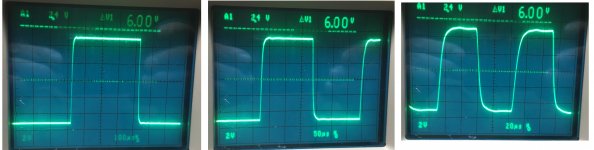
I used a variable caps and pots to come up with those goofy values. I definitely get less rounding with a smaller cap, but the leading edge is pretty ragged. I don't really mind a little rounding at 10kHz. I'm just surprised that I need such a big cap. Is there any problem with such a big cap. My frequency response doesn't seem to have suffered too much.
It's interesting that when I switch to UL with 12db feedback I don't need an input snubber or nearly as large a feedback cap. UL with 17db oscillates.
It's interesting that when I switch to UL with 12db feedback I don't need an input snubber or nearly as large a feedback cap. UL with 17db oscillates.
You need a larger value feedback capacitor in your case because of the low feedback resistor value. The time constant (R x C) is what matters. You can't really compare to what other people are using because it depends on the output transformer. If it sounds good and has good square wave response then there is no problem.
With UL you can get more feedback with an output snubber between the screen and plate taps.
With UL you can get more feedback with an output snubber between the screen and plate taps.
I have always found (with multiple different transformers and varying amounts of feedback dB) that the global feedback capacitor can be removed entirely, and adjustment of the 6.8k resistor and C7 is all that is necessary. Values always adjusted with a potentiometer and trial/error values of capacitance.
Make the step network capacitor (what you call the input snubber capacitor) a little larger and the feedback cap a little smaller. Also put the step network resistor on a linear pot, adjust it in real time to hone in on the square wave response you want, then measure and replace with fixed resistor when done. Ideally you want a little overshoot on the leading edge of the square waves, but damps after about one cycle.
If the output transformers are decent, you should be able to get closed loop small signal frequency response out to at least 40 KHz before it starts to attenuate. There's a trade off here though: the more aggressive you make the step network, the more it negates the effects of negative feedback at higher frequencies. It's always a compromise finding the right balance between frequency response and stability.
Also, test stability of the amp by running a 10 KHz square wave at very low power output, and try different types of load. It should be stable under any and all types of output loading conditions. The most brutal test seems to be a single cap-only load of between say 0.047 uF and 0.1 uF. Run the output stage at low power when attempting this. One-half to one watt is all that's needed.
Just curious, what make of output transformers are you using?
Last edited:
Thanks for the responses. I didn't realize that a little overshoot on the leading edge was desirable. On the pics I attached in the first post, there is a tiny overshoot.
Is it acceptable to have more of an overshoot? I can achieve that with much less capacitance.
I haven't tried loading the amp with a pure capacitance yet. :-O
Is it acceptable to have more of an overshoot? I can achieve that with much less capacitance.
I haven't tried loading the amp with a pure capacitance yet. :-O
That's not a "tiny" overshoot, in fact, it's way too much. Also, follow kward's suggestion, you should also check the square wave responses under no-load and capacitive load to verify the stability of the amplifier.I didn't realize that a little overshoot on the leading edge was desirable. On the pics I attached in the first post, there is a tiny overshoot.

I didn't design them. I lifted them directly from Merlin Blencowe's book "Designing Power Supplies for Valve Amplifiers," which he took out of print because he didn't like it, but I like it a lot and recommend it.Why did you design the output bias circuits as you have?
Hi mskl99,
Didn't he explain this in his book? I have one of his other books, but have not seen anything like this in there. I might be wrong, but it looks to apply negative bias quickly, but discharge more slowly. Maybe that makes turning off the amp doesn't make a thump noise. Otherwise, I'm at a loss on it. I don't like it when there is something I don't completely understand.
-Chris
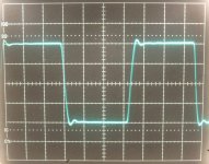
The first attachment is an example of what the square wave response looks like for a well tuned amp with really good output transformers. This particular example uses late model Fisher 400 outputs and 18 dB feedback. Small signal HF response is flat to 40 KHz with these, and -1 dB down at 50 KHz.
Hammond output transformers are not bad I guess...not as well wound as the Fishers. I don't have any experience with their newer "-A" versions with the "easy wire" secondary. All my experience is with their earlier versions that have multiple separate secondaries that you connect in various configurations to achieve the secondary impedances you want. With those models, my experience tells me it's best to pull the feedback signal from the 4 ohm tap--you get the most stability headroom that way.
The second attachment shows the best square wave response I was able to get with Hammond 1650H's. This example pulls feedback from the 4 ohm tap, and utilizes 18 dB feedback. Small signal HF response is flat to just barely 30 KHz, and -1 dB down at 35 KHz. The several amps I've built with Hammond iron present an interesting compromise in tuning. To get the amp unconditionally stable, I needed a quite aggressive step network--so much so that feedback (18 dB at 1 KHz) was partially negated at 15 KHz and totally negated at 20 KHz. But on the other hand, LF response was strong clear down to 30 Hertz at full power output.
Both amps I'm describing here are unconditionally stable (meaning, stable under any type of output load, including no load).
Attachments
Last edited:
While the optimum values vary with output transformer, most valve amps do seem to end up with a time constant in the region of 1.5 to 1.8 microseconds for the feedback RC. You are spot on 1.8us.I'm just surprised that I need such a big cap. Is there any problem with such a big cap.
Hi kward,
The current Hammond transformers are pretty good, but Hammond is in the process of redesigning the audio transformers in their line. Check out their new signal transformers they recently released.
The easy wire output transformers simply return to their really old wiring before those terrible windings you just used. I expect to see their engineer within a month and we will be talking about the new transformers (tube output stage types).
-Chris
Very cool anatech. Can't wait to see the new offerings from Hammond for tube output stages. I just feel there is a dearth of good quality, well wound, reasonably priced output iron, especially in that 6K to 8K PP range. I know people discuss Edcor as another option. I think Edcor's offerings are par. But I have had consistently better results with Hammond than I have had with Edcor.
What is "terrible" in that wiring "he just used"? To me it makes absolute sense as the secondary's copper is being used more efficiently. With the "old type of wiring" if e.g. only 4R is being used - the stretch from 4R -> 8R -> 16R becomes a waste. What s the point of it, cheaper production? du-h.
In my PP amp with Hammonds I have zero compensation networks, it is absolutely stable. I do connect 4-8R speakers (they are 8 but have the impedance dive at LF) to the 4R-commutated secondaries with awesome outcome.
I have same feeling that the return to "easy wire" manifests the end of quality. All OPTs will generally suite to the guitar combos, forget the Hi-Fi.
- Status
- This old topic is closed. If you want to reopen this topic, contact a moderator using the "Report Post" button.
- Home
- Amplifiers
- Tubes / Valves
- Compensation networks