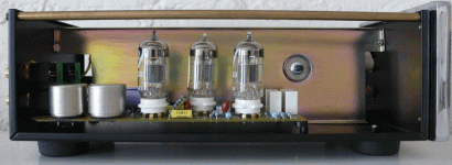
A friend of mine has an EAR834P phono preamp in for repair and noticed two fets in the front end, wired up as a cascode with the first 12AX7. This is not what the schematics circulating on the net show. Before anyone starts it is an original unit not modified. What gives? Schematic attached.
Attachments
It is a real 834P
Lucas has the real 834P, that is the one he is repairing. Again, what is strange is that the circuit widely available on the net, and attached below does not show the fet/12AX7 cascode. I have been told by several repair techs that what EAR schematics show and what is built are often quite different, as in this case. Whether this deliberate on EAR's part to throw off "clone" builders is up for debate.
Lucas has the real 834P, that is the one he is repairing. Again, what is strange is that the circuit widely available on the net, and attached below does not show the fet/12AX7 cascode. I have been told by several repair techs that what EAR schematics show and what is built are often quite different, as in this case. Whether this deliberate on EAR's part to throw off "clone" builders is up for debate.
Attachments
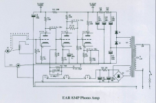
In earlier units I can verify no FETs. Must be a recent alteration. That schematic is over 10 years old. 834p has been in production since 96, so not unusual that it may have seen updates. Perhaps this is an effort to lower the noise floor? It’s at the input?
Any idea of their utility? Care to draw up a schematic? What FET?
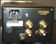
Edit: on second look there seems to be other changes / additions. Do you have a top down view photo?
Any idea of their utility? Care to draw up a schematic? What FET?
Edit: on second look there seems to be other changes / additions. Do you have a top down view photo?
Sorry
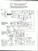
The unit Lucas had repaired is back with the owner, so no opportunity for a top shot. As to the fet, the designation was rubbed off and painted over. I suspect the addition of the fet to make a cascode front end was to boost the gain to better cope with the feedback RIAA. Noise may have been another consideration. The NYAL Super IT had a similar cascode front end, but passive RIAA. Schematic attached.
The unit Lucas had repaired is back with the owner, so no opportunity for a top shot. As to the fet, the designation was rubbed off and painted over. I suspect the addition of the fet to make a cascode front end was to boost the gain to better cope with the feedback RIAA. Noise may have been another consideration. The NYAL Super IT had a similar cascode front end, but passive RIAA. Schematic attached.
Attachments
The circuit in post #9 looks considerably less elegant than Wright's. The fact that the source resistors for the jfets are split and partially bypassed makes me suspect that the disguised jfets are something proletarian like a J113, which seems to be a fairly common go-to for escapades of this sort.
Better tubes and jfets would yield better results, but then, you'd have a totally different preamp anyway.
Better tubes and jfets would yield better results, but then, you'd have a totally different preamp anyway.
NYAL Superit
Wrenchone
The NYAL circuit was I believe designed by Brian Clark, who did design work for both NYAL and GSI in the early 80's. Clark also wrote several articles for The Audio Amateur in 1981-82 about phono preamps and equalisation. As to his design choices for the Super IT, I suspect quality jfets for audio (high transconductance, low noise) were hard to get and mega expensive then. Toshiba jfets had very limited distribution outside of Japan hence I think you are right about being a J113 or similar. Levinson's JC2 had the E110 jfet for example, which were nothing to write home about.
Clark's SuperIT was the first example of this jfet/tube cascode in a phono preamp that I know of. Talking with the late Allen Wright about his preamp, the SuperIT predated his. I also believe Arthur Loesch experimented with this idea and David Berning used a jfet/tube combination (although not cascode) in his preamp around the mid 70's. Like the circlotron circuit, a lot of people were thinking similar things around about the same time. Oh and before I forget, the SuperIt sounded quite good given its cheapness
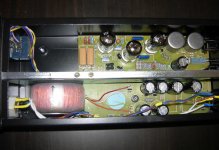
I could not find any of mine, but I got a photo of one that a friend was thinking to buy.
This was around 2013. And yes, you can see the solid state stuff are there. WoW... never noticed it before. Now I need to know about the one I had")

This was around 2013. And yes, you can see the solid state stuff are there. WoW... never noticed it before. Now I need to know about the one I had
Attachments
Last edited:
Wright's design came to mind reading the original post. His design, the FVP/SVP, uses the FET to provide the additional gain, with low noise, to make the amp suitable for MC carts (as well as MM ones ,gain is adjustable via the source resistor). Looking at the i/p configuration of the cct in post 9, it looks like it is there to achieve the same aim.
Wright's FVP5a circuit is below.

Wright's FVP5a circuit is below.


- Home
- Amplifiers
- Tubes / Valves
- EAR834P is not what it seems