To be more helpful here are some things that could be addressed
Essentially, an amplifier with the "shape" of the circuit shown has the potential to be very good, but many of the design details will be different for it to be truly Hi-Fi. I believe Eli Duttman has a circuit that may fit the bill perfectly.
- Change the biasing arrangement so each valve can individually be trimmed, using low value cathode resistors on the order of 10 ohms
- Add negative feedback (may get interesting with the number of the AC coupled stages)
- Use a more conventional CLC supply
- Probably use valves more linear than the 12AU7 throughout the front end
Essentially, an amplifier with the "shape" of the circuit shown has the potential to be very good, but many of the design details will be different for it to be truly Hi-Fi. I believe Eli Duttman has a circuit that may fit the bill perfectly.
Last edited:
Along with what's recommended above by Bigwill:
Omit the third stage (tube connected to R10/R11).
You will absolutely need global negative feedback or some feedback around the 6L6's. Depending on how much you use, it may help to use a 12AT7 instead if your tweaks overly desensitize the amp.
The original schematic may have been OK for audio frequencies that you'd get out of an AM radio.
The circuit resembles Williamson topology. Key differences lie in cap. coupling the voltage amplifier to the phase splitter and the absence of a GNFB loop.
Bigwill is correct about very poor linearity. Simply adding a GNFB loop is a very bad idea. Low frequency instability is THE weakness of Williamson style circuitry. Adding an additional pole to the mix exacerbates the problem.
I intensely dislike 'U7 voltage amplifiers, as the type is distinctly non-linear.
While there are details I would change, 2 Heath Williamson setups (W5M/W6M) are provided as references.
Attachments
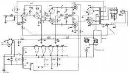
There is nothing wrong with this design in principle, although I agree that 12AU7 is not the best choice. It is decidedly not a Williamson circuit. It uses ingenious DC-coupled cathode followers that allow AB2 operation without problems of the more traditional transformer-coupled design.
Lack of global negative feedback is advantage rather than disadvantage. Without NFB, the amplifier works as current source, which reduces speaker distortion. Without NFB, speaker, which is a reflective load, is isolated from the amplifier input, and doesn't send time-delayed speaker distortion signal into amplifier. You just have to use the right speaker with this amp, the one that doesn't depend on electric damping.
Choke input power supply has better regulation than capacitor input supply, which is critical for correct operation of an AB2 stage. Capacitor input supply would be a big downgrade.
This circuit is NOT frequency limited, as long as good output transformer is used. It has low distortion. It is a genuine Hi-Fi amplifier.
It can be further improved, of course. If I was to build a circuit like this from scratch, I would use 807 tubes instead of 6L6 and B+ or 700-750 V. I would use regulated supply for screens and CF driver. I would use full-wave rectifier for the negative rail. I would use fixed bias for cathode followers to improve bias stability and get rid of electrolytic capacitors. Of course 6SN7 in place of 12AX7. Coupling capacitors from phase splitter need not be 0.1; 2,000 pF is enough because CF input impedance is very high.
What I am saying is not some theoretical speculation. I have 60W Allen amplifiers using the same topology, but better design, as one can judge from the attached schematic. They are wonderful amplifiers.
Attachments

I need to add that "B2" portion of Class AB2 operation of this circuit is quite limited due to low idle current of cathode followers. Running them at higher current may enable full-throttle AB2, squeezing 120 W out of a pair of 807s. But that will require more powerful CF tubes and re-design of both positive and negative CF supplies.
You just have to use the right speaker with this amp, the one that doesn't depend on electric damping.
So you need a speaker from an old AM radio?
So you need a speaker from an old AM radio?
Exactly. My favorites are 12" field coil Magnavoxes (there are many models differing in FC and VC resistances, as well as cone design. They have small diameter voice coils, low Le, low Mms, and 95 dB sensitivity. They are reasonably full range (60-8,000) and easily crossed second order with Bohlender Neo-3 planer tweeters.
One important advantage of FC motor is virtual freedom of distortion caused by modulation of gap magnetic field by VC magnetic field.
This is a vast and interesting topic in itself, but it belongs to speaker forum, so I am stopping here.
It is very odd. 6L6G had an AB2 suggested condition: 47 Watts (not 30W).
Most sweep tubes do NOT have AB2 ratings. We do not have a maker-approved number for how much grid Power is safe.
The lack of NFB is debatable. Even if I liked current drive, for Hi-Fi I'd want current feedback for amp linearity.
25 Watt pot??
The self-biased 12AU7 stage may drift and upset 6L6 bias-- this could be done otherwise.
One thing not odd: it sells a lot of 12AU7 (consider the source).
With improved "6L6" (the only kind sold now) and more B+ you can easily get 40W, 50W, even maybe 60W/pair.
The lack of NFB is debatable. Even if I liked current drive, for Hi-Fi I'd want current feedback for amp linearity.
807 pentode stage with Ua>>Ug2, stable supply voltages, and fixed bias has better open loop linearity than 2A3.
807 pentode stage with Ua>>Ug2, stable supply voltages, and fixed bias has better open loop linearity than 2A3.
The linearity may be quite acceptable, but the damping factor is not. Some form of NFB is needed in order to obtain satisfactory voice coil control.
807 pentode stage with Ua>>Ug2, stable supply voltages, and fixed bias has better open loop linearity than 2A3.
In AB2? With a mere 12AU7 to flog the grids?
- Status
- This old topic is closed. If you want to reopen this topic, contact a moderator using the "Report Post" button.
- Home
- Amplifiers
- Tubes / Valves
- Any thoughts on this GE design