I'm working on designing the PSU for a new push-pull tube amplifier using 4x 6550 tubes. It will be a williamson-ish amplifier built in the chassis of my Bewitch 6550 (cheap Chinese amp) with the original OPTs (for now) since they are pretty decent.
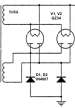
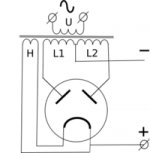
The power transformer is not centre-tapped, so I will be using 2x UF4007 diodes for the current return path (ground side of the bridge rectifier) and 2x 5AR4 / GZ34 tubes working full-wave in parallel for B+ (see schematic photo for clarification; the diodes labeled 1N4007 will be UF4007). I know this isn't ideal, but I'm not going to re-wind the transformer just to have a centre-tap there.
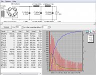
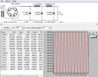
So, I ran this through PSUD II with the rectifier set to 5AR4 x2 bridge, which is the closest match I could find. It looks good to me. However, I want to be sure the initial current spike in the simulation (current at BR1, L1, and L2) won't be an issue. The spike only lasts a few hundredths of a second. Can someone reassure me that this is fine, or tell me if I'm being an idiot?
For the circuit, refer to the schematic in PSUD II with the exception of the bridge rectifier, which is modified with two SS diodes as mentioned previously. The chokes will be Hammond 159V (1.5H, 27Ω, 500mA) and Hammond 159Y (600mH, 11Ω, 750mA).
Also, if you have any feedback about the rectifier circuit in general (e.g. suggestions for improvement), I'm all ears. Thanks!
The power transformer is not centre-tapped, so I will be using 2x UF4007 diodes for the current return path (ground side of the bridge rectifier) and 2x 5AR4 / GZ34 tubes working full-wave in parallel for B+ (see schematic photo for clarification; the diodes labeled 1N4007 will be UF4007). I know this isn't ideal, but I'm not going to re-wind the transformer just to have a centre-tap there.
So, I ran this through PSUD II with the rectifier set to 5AR4 x2 bridge, which is the closest match I could find. It looks good to me. However, I want to be sure the initial current spike in the simulation (current at BR1, L1, and L2) won't be an issue. The spike only lasts a few hundredths of a second. Can someone reassure me that this is fine, or tell me if I'm being an idiot?
For the circuit, refer to the schematic in PSUD II with the exception of the bridge rectifier, which is modified with two SS diodes as mentioned previously. The chokes will be Hammond 159V (1.5H, 27Ω, 500mA) and Hammond 159Y (600mH, 11Ω, 750mA).
Also, if you have any feedback about the rectifier circuit in general (e.g. suggestions for improvement), I'm all ears. Thanks!
Attachments
Last edited:
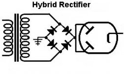
If you are going to use a bridge rectifier, and at the same time use tubes I would recommend trying a hybrid rectifier, such as this. Using only tubes in a bridge rectifier is not the usual way of doing things, reasons for this is among others the rp of the tubes. if you don't want to use ss, use a two way rectifier with only tubes.
Attachments
Last edited:
I assume this is going to be a stereo chassis build? Driving both channels simultaneously to full power could be taxing on the 5AR4s. Would need to see the full schematic with details to comment further.
This hybrid rectification approach on a big amp like this would not be my first choice.
This hybrid rectification approach on a big amp like this would not be my first choice.
PSUD is needlessly limiting. Use a normal circuit simulator so you can model your intended circuit and get the full picture. It would be better to use a full bridge rectifier and simply place the tube diodes after it. This puts less stress on the tube/s. You can then also model the tube in PSUD as a simple resistor.
Attachments
Last edited:
A 5AR4 is good for 250 mA. of B+. The pair the OP plans on using are good for 500 mA. This KT88 data sheet indicates that 500 mA. might be insufficient, when both channels are producing full power. If a hybrid bridge rectifier is to be employed, 2X 6CJ3s should provide the currently handling ability needed. Of course, the power trafo is the ultimate limiting factor.
FWIW, I'd use the 3 A. UF5408, instead of the 1 A. UF4007. It's a belt and suspenders mind set.
FWIW, I'd use the 3 A. UF5408, instead of the 1 A. UF4007. It's a belt and suspenders mind set.
If resistance is required at this point, I can't see the benefit of replacing it with an equivalent tube diode.place the tube diodes after it.
I'm just saying that you can model the circuit reasonably well in PSUD by using a resistor in place of the tube diode. And yeah, the only point of using the tube diode in reality is for the gentle warm up time (may be useful to the OP, who knows) and of course the coolness/novelty factor.
Get a $7 time delay relay.
Using solid state rectification is not a bad idea and I will consider it.
I have found some designs for time delay circuitry, but I have never seen a COTS time delay relay for such a low price. Can you provide an example?
Thanks!
Using solid state rectification is not a bad idea and I will consider it.
I have found some designs for time delay circuitry, but I have never seen a COTS time delay relay for such a low price. Can you provide an example?
Thanks!
12VAC/DC 0-60 Seconds Power Off Delay Time Relay With Socket Base | eBay
Or this for even less.
NE555 Single Channel Relay Power On/off Delay Module Timing Switch 1-15s Adjust | eBay
Cheers.
I use them to switch 120VAC for the primary of the power transformer and they are fine. Ratings are quite conservative. I've used 60V wire for 500V without issue because the current is low. I've used 12V 40A relays to switch 450V without issue.
I would say the first one listed will work anyway, and the second one might (smaller relay, smaller air gap). I use separate heater and HV supplies so it makes it easier. If anything if you're using a center tapped transformer you can use it to lift the ground connection.
I would say the first one listed will work anyway, and the second one might (smaller relay, smaller air gap). I use separate heater and HV supplies so it makes it easier. If anything if you're using a center tapped transformer you can use it to lift the ground connection.
- Status
- This old topic is closed. If you want to reopen this topic, contact a moderator using the "Report Post" button.
- Home
- Amplifiers
- Power Supplies
- PSU design check