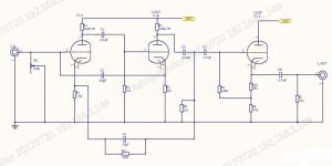
you can split the 47k r9 in two 27k resistors, one at the plate
and the other are the cathode side where the 47l was at the'cathode flower, or last stage" provide blocking caps at the plates...
the cathode side in non inverting while the plate side is inverting...
and the other are the cathode side where the 47l was at the'cathode flower, or last stage" provide blocking caps at the plates...
the cathode side in non inverting while the plate side is inverting...
Thanks for your advise, could you draw a pic to help me understand it?
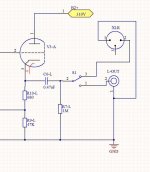
And I want put a switch to give me option to get balance output(XLR) and unbalanc output(RCA), is your method can do it?
And I want put a switch to give me option to get balance output(XLR) and unbalanc output(RCA), is your method can do it?
Here are the steps:
1. Connect the center pin of the output RCA jack to XLR pin 2.
2. Connect pin 2 to the chassis grounding tab provided by the jack.
3. Connect a 0.47uF cap and 1M resistor to pin 1. The 1M resistor connects to ground. The 0.47uF cap needs to go to ground through a resistor that's equal to the output impedance of the preamp (measure it if you aren't sure).
The cathode follower is pretty crappy as it is, I wouldn't make it into a split load PI!
Step 1 is OK, since XLR pin 2 is +, so it will connect to the center pin of RCA jack
Step 2 confused me, why connect pin 2 of XLR to the chassis grounding tab of output RCA jack? It will ground the + of XLR, is it right?
Step 2 confused me, why connect pin 2 of XLR to the chassis grounding tab of output RCA jack? It will ground the + of XLR, is it right?
Here are the steps:
1. Connect the center pin of the output RCA jack to XLR pin 2.
2. Connect pin 1 to the chassis grounding tab provided by the jack.
3. Connect a 0.47uF cap and 1M resistor to pin 3. The 1M resistor connects to ground. The 0.47uF cap needs to go to ground through a resistor that's equal to the output impedance of the preamp (measure it if you aren't sure).
Sorry, made a typo or two. Need more coffee!!!
You could do as Tony suggests but not with a 12AX7A, more suitable candidates would include the 6DJ8, Russian 6N6, 6H30 or similar. You would need a LOT more plate current, say about 10mA or so.
yes, desiderata for cathode followers, high mu and high transconductance...i use the 6kn8 or the Japanese 6RHH8, 6N23, 6N30, ecc88, etc...
the 12ax7 while having a mu of 100 has a transconductance of 1,250mmhos at 0.5mA, and ecc88 otoh, has a transconductance of 12,500mmhos at 15mA, 90v, mu of 33...
this topology has an almost cult following, i do get a lot of request to build a marantz 7 line amp clone....
the 12ax7 while having a mu of 100 has a transconductance of 1,250mmhos at 0.5mA, and ecc88 otoh, has a transconductance of 12,500mmhos at 15mA, 90v, mu of 33...
this topology has an almost cult following, i do get a lot of request to build a marantz 7 line amp clone....
how far away is the power amp going to be?
maybe i'm on the outside of the curve but with no net sonic benefit why? unless your talking about having the pre-amp drive a 150 foot line because the power amp is that far away what's the point of going balanced?
maybe i'm on the outside of the curve but with no net sonic benefit why? unless your talking about having the pre-amp drive a 150 foot line because the power amp is that far away what's the point of going balanced?
turk made a great point. Balanced connections are for long distances in noisy environments. Think pro audio or a concert hall. Pretty much a waste of time in a home stereo system. Plus your going to kill the resale value on a very expensive and desirable preamp.
Because my power amplifier is MC-275 with XLR input, and I would like to use XLR for comparison to RCAturk made a great point. Balanced connections are for long distances in noisy environments. Think pro audio or a concert hall. Pretty much a waste of time in a home stereo system. Plus your going to kill the resale value on a very expensive and desirable preamp.

You mean like this?
View attachment 635821
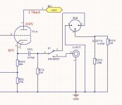
R13=(310-84)/0.00176=128K(12AX7 inner resistance)
Is it correct?
No, if the output impedance of your preamp was 128K, you wouldn't be using it!
With a couple of clip leads, a multimeter, and a 10K pot, you can measure this yourself.
You have a Cathode Follower output. For your particular design the output impedance should be around 550 ohms not 125K.
if an xlr "sounds" different than an rca on a short run something else is wrong.
there should be no discernible difference between the two.
there should be no discernible difference between the two.
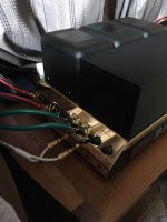
Ugh, it's really too bad that you have the new MC-275 with the XLR inputs. The unbalanced inputs go to both the first stage and to what they call a "unity gain buffer", which is a voltage divider feeding a grounded cathode amplifier to invert the phase. The problem is that the voltage divider will never be a particularly wonderful way to cancel out the gain provided by the tube (looks like a 12AX7), as there will be a bit of a difference in gain from one tube to another.Because my power amplifier is MC-275 with XLR input, and I would like to use XLR for comparison to RCA
View attachment 635772
This wouldn't be that big of a deal if there was a well balanced differential stage at the input of the amp. For unbalanced operation, one grid could be grounded, and for unbalanced operation, you'd just tie the other grid to Ve- on the XLR jack.
For the XLR input on this particular amp, there's also an assumption that both legs are driven with equal and opposite signals (not a responsible assumption to make). The ideal thing to do in this particular case for you is to buy a pair of output transformers for your preamp if you want to try the XLR inputs, but this further complicates things since you need to drive the miller capacitance sitting at the input and your preamp isn't going to be too happy driving a low impedance load.
In the end, just stick to your unbalanced connections.
- Status
- Not open for further replies.
- Home
- Amplifiers
- Tubes / Valves
- How to add balance output to C22


