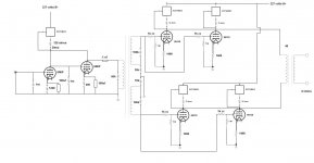
I've taken another stab at a schematic. I can see why the 100 volt/90ma route would make sense. Less voltage swing and from what I know of load lines less distortion. But I already have the power transformer and I want to extract as much power from the amp as I may. This amp is an experiment as much as anything else.
As for the schematic. I added grid stoppers and cathode resistors instead of sinks. In one way the cathode resistors work out well because with the B+ I have the voltage dropped across the cathode resistors will mean 250 volts across each tube. At 1400 ohms it seems like the cathode resistors should be bypassed? I still have to figure those out.
The interstage design is lifted from the original Magnavox schematic.
As for the front end I thought using a CCS set to 20ma and letting the cathode resistors for 6N6P/ECC99 divide the current between them might work. I might be wrong on this. Also, it would be nice to DC couple the two voltage amps if it will work. The .1uf coupling cap acts as a parafeed for the interstage to keep the DC out of its primary.
The glaring errors will be easy for everyone to spot so constructive criticism is welcome.
Attachments
Running the outputs with CCS loads brings almost nothing good to the party in this application. Since the Output transformer has a fraction of the impedance of the CCS it will dominate the distortion generating components. It will also limit your output swing - and I suspect will probably fry the CCS when the OT tries to swing higher than the B+ and reverse the drain and source voltages.I've taken another stab at a schematic. <snip>
If you are going to use CCS's anywhere in this circuit it would be in the front end and in the cathodes of the 6080's. Running the 6080's with CCS in the cathodes has specific benefits which have to be understood as they come at the cost of limiting the circuit to low power class A operation (good for low distortion and DC intolerant transformers but little else). Putting CCS in the cathodes of circuits has become somewhat trendy but rarely do the people doing it understand the consequences.
I would get familiar with the joys of SPICE and model all of these ideas to see what is possible. I have taken raw ideas and refined them to workable circuits this way and learnt a huge amount along the way.
Shoog
Last edited:
Hey anyone, I'm back to TL783 as a constant current sink at the cathode of the outputs. The reference voltage across the parallel resistor is 70 volts. The same as it would be using a 1400 ohm cathode resistor. But the actual current would be through the regulator. The drop across the regulator is 1.3 volts maximum. If I understand this correctly the actual drop through the CCS will be something less than 1.3 volts. So 251.3 across the tube and the CCS would leave about 77 volts unaccounted for. That means I could use a 1.54k plate resistor or larger if I wanted to drop 250 or more across the tube? Also without the huge cathode resistor I wouldn't have to bypass it would I?
Last edited:
Some mess detected.Hey anyone, I'm back to TL783 as a constant current sink at the cathode of the outputs. The reference voltage across the parallel resistor is 70 volts. The same as it would be using a 1400 ohm cathode resistor. But the actual current would be through the regulator. The drop across the regulator is 1.3 volts maximum. ..
I just can't get what the circuit you intend (( If that is a CCS - what "cathode resistor" are you talking about?? If CCS - then the drop across the TL is 70V - 1.3V. If you "load" TL with a resistor to make TL less heating (as you say the 1.3V drop across it) in this case the TL provides no (nil, null, zero) CCS performance. Aka "useless".
From how your design is progressing I feel that without those my other words your last reply would not be such a short sentence. You got what you asked for. .. be grateful )).. .all the answer I needed.
The problem with CCS at the anode is that the voltage swing is highly limited.
With normal PP circuit, the transformer at the anode, the voltage swing is almost from 2 x +Ub to Uk but with CCS only from +Ub to Uk.
In practice this means that with normal transformer coupled PP, with 375 V +Ub the max. voltage swing at the anode is some 550 V to 190 V = 360 Vpp.
With CCS at the anode the max. voltage can not be more than +Ub, less the voltage required by the CCS to operate.
In case of the below simulation the voltage swing is some 300 V - 90 V = 210 Vpp.
And as we know the power is: U² : R. Therefore the latter voltage swing produces only 1/3 of the power of the first.
Second problem is the OPT. It seems to be 4k. This is not optimum for parallel PP.
Some 2k to 2k5 would be ideal.
With your last circuit, only some 5 W of output power is expected.
One advantage is however achieved, the THD is very low.
Attachments
Thanks very much Arto. I have a Japanese LCR meter on the way that can measure up to 2 kilo-henries. My current meter's limit is 40 henries so I couldn't even measure the interstage. When I recieve it I'll be able to really model the amp in Spice and that will make things much easier for me. And I won't have to lean on you guys as much.
The output transformer isn't ideal but they were free. My winder can build me custom outputs for about $90 each. So I may go that way instead.
Thanks again, Kevin
The output transformer isn't ideal but they were free. My winder can build me custom outputs for about $90 each. So I may go that way instead.
Thanks again, Kevin
I'm afraid your post makes aboslutely no sense to me. If used as ccs, the drop across the regulator will be whatever it takes to achieve the desired current. The 1.3V is just the minimum to get the regulator chip working. If using a ccs, you don't need to add resistors here or there to adjust. In fact, the additional resistors will do more harm than good. The ccs will automatically adjust its voltage drop as stated above.Hey anyone, I'm back to TL783 as a constant current sink at the cathode of the outputs. [...]I?
If you want to burn less heat in the ccs, just lower your Ub+.
You will need to bypass the ccs'es if you're going to use 1 per cathode.
Almost all 6080 pp circuits operate in class A anyways due to plate voltage limitations (250V) and the yuge voltage swing required for the drivers (~280Vpp for 5K Ra-a opt @13W class A power).Running the 6080's with CCS in the cathodes has specific benefits which have to be understood as they come at the cost of limiting the circuit to low power class A operation (good for low distortion and DC intolerant transformers but little else).
one more question sir if you will, instead of CCS would blumline garter circuit balance current enough to use torriod power trans for output?
Lawrence
late reply, I know, but curiously I've been seeing a bunch on this idea lately, so I'll bite.
I've done it, and love it. Wasteful yet wonderful.

165v B+ for the 6AS7G (I used winged "C" 6n13S) a simple isolation transformer (115/120v) rectified and with a cap slapped on works perfectly.
330R/10w cathode resistors, cheap wirewound noninductive work well and are affordable.
Ends up about ~33 volts across each R, ~100v/100mA across each tube.
Sounds fantastic, and works well with 1200~2000ohm plate-to-plate output transformers.
Use a dual secondary transformer, and rectify both windings, and stack them on top of eachother. This gives you ~165v and ~320v or so to play with. Filter the 320~ with a basic pi filter, and run a 12AT7 or 6SL7 amp/phase inverter to feed it.
I built up a five channel version a while back, made a nice space heater for use in a cold garage that doubled as a home-theater hangout room. With a powered subwoofer it was fantastic.
Hey Lingwendil! Do you think the 6SL7 floating paraphaseinverter from the Acrosound 6L6 amp would drive 4 sections of 6AS7? I want to make a 2 output tube /channel version using 120:120-24 ~600R:6R VPT48 transformer. The chassis is already wired to that phase spiltter so I guess I could try it and see.
Cheers.
Cheers.
You talking about this circuit, right? https://elektrotanya.com/PREVIEWS/63463243/23432455/oldies/acrosound/acrosound_6l6_280_sch.pdf_1.png
If so, it probably should just fine, even if I really don't care for paraphase. I have a Chinese PCB that uses that same circuit but with the 6V6, and I'm going to do some creative wiring to convert it to a standard LTP and run a CCS under it, but it would give less gain for your situation. My bias aside, I think it will work.
If so, it probably should just fine, even if I really don't care for paraphase. I have a Chinese PCB that uses that same circuit but with the 6V6, and I'm going to do some creative wiring to convert it to a standard LTP and run a CCS under it, but it would give less gain for your situation. My bias aside, I think it will work.
Well as it turns out it wasn't still wired like that, I was using a transformer in this chassis before. Now I get to start from scratch. I have two sockets already, and can put in two more. Perhaps the standard Williamson? Gain/splitphase/gain or cathode follower. I have two octal sockets in it already so I'd rather not use miniatures. I will probably use a feedback loop but I usually don't do much more than 6db or so. Oh and I already have lots 12SN7 and 6SL7 on hand.
A Williamson would work, maybe 6SL7 gain/concertina, 6SN7 differential, then 6AS7. I wouldn't bother with cathode followers, since the 6AS7 will work great with 1M grid resistance, so even at 470k per phase it's still no sweat for the 6SN7. Could probably get away with all 6SN7 front end if your sources are hot enough. 6SL7 gives more wiggle room. Could go half a bottle per channel for gain and leave out the concertina if you have a CCS under the differential tail.
1/2 6SL7 feeding a 1/2 6SN7 concertina would be the way I would go if you have a hot enough source to drive the 6SL7 far enough to clip the finals, but you're on the edge of usable gain for feedback that way... it would also need 350~400 volts to keep the 6SL7 bias in a good spot to accept the required signal, and it would do best with a CCS to squeeze out maximum swing/linearity.
1/2 6SL7 feeding a 1/2 6SN7 concertina would be the way I would go if you have a hot enough source to drive the 6SL7 far enough to clip the finals, but you're on the edge of usable gain for feedback that way... it would also need 350~400 volts to keep the 6SL7 bias in a good spot to accept the required signal, and it would do best with a CCS to squeeze out maximum swing/linearity.
Last edited:
- Status
- This old topic is closed. If you want to reopen this topic, contact a moderator using the "Report Post" button.
- Home
- Amplifiers
- Tubes / Valves
- 6AS7GA as push pull output?