")

Have a nice Sunday
Attachments
-
 1775A7A5-F6A6-417D-A032-52FEE48DB507.JPG724.2 KB · Views: 252
 -
 DDC76F6E-E2DB-4042-AEC7-89AB2E3B379F.jpg301.7 KB · Views: 914
 -
 C1937DB4-36AD-47B2-8B63-1CDD83532595.JPG161.1 KB · Views: 990
 -
 ACAC7C96-546D-42C0-AA86-CF6C85CB4579.JPG426.1 KB · Views: 535
 -
 94AA8169-CAC5-4A30-8FD0-DAE6FE7711B4.jpg306.3 KB · Views: 550
 -
 01F90CDB-5E07-4FA2-9FFB-240D872899EE.JPG325.8 KB · Views: 352
 -
 C7127860-975D-4510-8D6A-0805C4778FEC.jpg269.8 KB · Views: 549
 -
 8F1F680F-1D9C-4E0B-B5BB-802C3948AC74.JPG601.4 KB · Views: 542
 -
 1C2605DF-51DA-4C70-91CA-C91E70EA8B3C.JPG116.3 KB · Views: 381
thank's thank's thank's !!!!

merci merci merci !!!
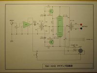
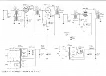
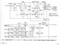
OK... Now could somebody tell me how do we read this? I'm interested in the feedback scheme.MJ1803_(04)MJ ZOOMUP_iPurifier-AC.pdf - Google Drive
OK... Now could somebody tell me how do we read this? I'm interested in the feedback scheme.MJ1803_(04)MJ ZOOMUP_iPurifier-AC.pdf - Google Drive
It's not perfect by any means but you get the idea...
Google Translate
Upload the PDF on that page and tell it to detect the language on the left and english or whatever you prefer on the right. Click translate and you get a new page with the translation.
It's laid out like the document so if you keep that open while looking at the text it'll help you keep track of what you are reading. For example, in the intro it looks like he used a pre-made chassis and to fill the hole for the rectifier tube the 0C3 was added.
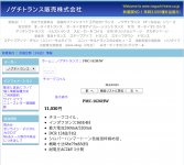
Component reference help to find missing PMC-1626HW data for example :
PMC-1626HW [pmc-1626hw] - 11,030円 : Zen Cart [日本語版] : The Art of E-commerce
PMC-1626HW [pmc-1626hw] - 11,030円 : Zen Cart [日本語版] : The Art of E-commerce
Attachments

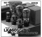
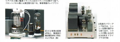
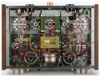
The amp a 211 driving a 211 can't imagine what the micro-phonics must be like.
Possible to ask Mr Mayer who is experienced with such 211 amplifiers
VinylSavor: 211 drives 211 Monos with Mercury Vapour rectified Power Supplies
here's some (some are not Japanese),
simpletube (Korea)
tossi (Japan)
Nagashima's Designs (Japan)
diyzone
Svetlana Technical Bulletins
Schematic Heaven (Guitar Amps)
simpletube (Korea)
tossi (Japan)
Nagashima's Designs (Japan)
diyzone
Svetlana Technical Bulletins
Schematic Heaven (Guitar Amps)
Thanks Soundhappy! Nice thread!
I fully agree MagicBus with you and other DIYers. Thank you Soundhappy. The diverse and "outpouring" of schematics in this thread inspired me to assemble a Class aP 12AX7A headphone amp. It sound great.
Best
Anton
OK... Now could somebody tell me how do we read this? I'm interested in the feedback scheme.MJ1803_(04)MJ ZOOMUP_iPurifier-AC.pdf - Google Drive
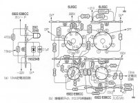
It looks weird at first look, but it is typical G3-K connection as a lot of pentodes have internal connection.
I assume you mean the input tube and yes I understand that. I also understand the partial feedback at the power tube - 220k from plate to g1. It seems there are some calculations for the cathode resistor of the input tube wrt the global feedback that I can't follow and not least the connection of the power tube g2 to the driver's cathode, to my understanding another form of feedback.
OK, cathode resistor is 680+51Ω for matsushita 6EJ7 or 680Ω for toshiba 6EJ7 written on right side of the picture.The power tube G2 is driven by the driver, it is not a feedback.This both G1 G2 driving circuit is used by the writer Soya Susumu many times, though, I do not see its clear benefit.
- Home
- Amplifiers
- Tubes / Valves
- Gold mine of DI¥ audio tubes schematics from Japan