Thank you 45, can you draw a picture to explain how to arrange the layers of winding?
I can't do drawing at the moment...but it's not difficult.
The simplest way is to split your initial scheme in two halves inserting a spacer in the middle of the coil former. This will also help to redistribute capacitance for better frequency response. You basically will make two coils...
On each half you will get 1/2 turns per layer (likely a bit less because the intermediate spacer will take some space).
So the first and the last primary will have 1/2 while each primary inside will have two layers.
This way you will also split the secondary in two equal parts. The blu in your drawing on one side and the green on the other side. Each secondary will have two layers.
An even simpler way is that you keep your original scheme except that you make the first primary (number 1 in your scheme) with larger wire so that you have 1/2 turns in the same space.
Then you complete the transformer with another identical primary at the end (i.e. primary nmber 9 identical to number 1).
As the primary turns are all in series it will be fine.
Then you complete the transformer with another identical primary at the end (i.e. primary nmber 9 identical to number 1).
As the primary turns are all in series it will be fine.
An even simpler way is that you keep your original scheme except that you make the first primary (number 1 in your scheme) with larger wire so that you have 1/2 turns in the same space.
Then you complete the transformer with another identical primary at the end (i.e. primary nmber 9 identical to number 1).
As the primary turns are all in series it will be fine.
You mean like this?

Diving the prim into 10 layers(5 for the left and 5 for the right), for each layer turns=N1/10 and series connected this 10 layer finally. As for the secondary B+~C used 4 layer, 2 put in left and 2 put in right for each layer turns=N2/2 and parallel connected this 4 layers, and for C~B- is the same as B+~C
Is that correct?
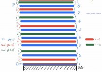
You mean like this?
View attachment 630537
Diving the prim into 10 layers(5 for the left and 5 for the right), for each layer turns=N1/10 and series connected this 10 layer finally. As for the secondary B+~C used 4 layer, 2 put in left and 2 put in right for each layer turns=N2/2 and parallel connected this 4 layers, and for C~B- is the same as B+~C
Is that correct?
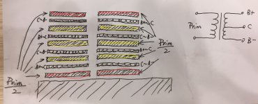
No! The first and the last primaries on each side always need to have 1/2 turns of the others. Otherwise no simmetry. So if the the first primary (closer to the core) and the last have 1 layer then the other primaries inside should have 2 layers.
If you want to do the primaries inside with one layer then the first and last will use bigger wire size to put 1/2 turns in one layer.
Connections for the secondary don't change respect to your original drawing if the primaries are all in series. You can have the blue on left and green on the right or cross-connect. See which gives the best response. If you have windings with 2 or more layers put some insulation between layers (0.05mm minimum).
As I said the easy way is that you stay with your original drawing except that the first primary (near the core) is made with larger wire so that you have 1 layer with 1/2 turns in the same width. The remaing 1/2 will be at the end.


- Status
- This old topic is closed. If you want to reopen this topic, contact a moderator using the "Report Post" button.
- Home
- Amplifiers
- Tubes / Valves
- Audio Note M10 Clone