Could you elaborate a bit more on the voltage gain of the 5687 stage?
I understand that the gain is lowered because of the unbypassed 1k cathode resistor, but by how much? (I am not good in interpreting sims...)
A gain of 1.4 (25:18???) seems very little.
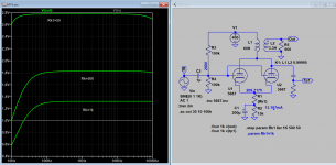
Here is the linear plot, the level on left hand side scale divide by the input (1V) is the gain. i.e. from top 2.7, 1.8, 1.35 with Rk1 55, 500, 1k respectively. This is based when the primary reflected impedance is about 10k with 60H primary, and voltage step down ratio: sqrt(60/3.3)~=4.6 (inductance H ratio is same as impedance Z ratio)
That is the voltage at the plate is divided by step down ratio, the gain is lost.
Attachments
Last edited:
Your points are well taken, but it is what it is... AN designed it that way.It only says step-down ratio. If that is turn step down then it's no good. Nothing tedious. With just 300V supply and limited inductance it cannot be HiFi for general use. A HiFi preamp is supposed to give typically at least 2-3 V RMS with THD of 0.1-0.2% or less from 20Hz to 20KHz. That's the minimum! This is not going to be the case if 33:1 is the turn ratio and run the tube at 10 mA.
This is getting too confusing, if you are going to run simulations, please at least do it with the parameters that AN provided, e.g., "But even a load of 600R results in a reflected load of 194k...", from which, the step down ratio is clearly not 4.6...This is based when the primary reflected impedance is about 10k with 60H primary, and voltage step down ratio: sqrt(60/3.3)~=4.6 (inductance H ratio is same as impedance Z ratio)
Your points are well taken, but it is what it is... AN designed it that way.
Eh OK, but does it mean that is good thing to copy anyway?
Even if one stretches all numbers to make it work reasonably well a simple, properly made, common cathode preamp is likely to work and sound better!
The OP is now also pointing out that he is not convinced. Even without taking into account the output transformer bottleneck....
Just to sum up:
The output transformer with 33:1 turn ratio needs to have at least 150H if 10mA current is used (or 120H if 15 mA anode current is used) in order to get 2 Vrms down to 20Hz with reasonably low distortion (which means likely worse that any other solution). This means a lot of turns on reasonably sized transformer. A lot of turns mean that geometry is not going to be simple otherwise high FR is going to be compromised and higher copper loss.
Exotic cores are not going to help much beause it's a gapped transformer. Best choice it will likely be Hi-B core.
Then effective anode voltage of the output stage has to be enough to provide about 70-75V rms at the primary with low distortion and away from any possibility of grid current.
Is this worth doing when it can be a lot better with much less trouble? I mean even if one wants to use an output trnasformer it can be a lot better with lower step-down turn ratio.
Thanks Koonw!
As I see it now, the output stage (that is 6072 SRPP cascaded into 5687) before the output transformer has a gain of 20 x 5.6 = 112. 5.6 is your simmed 1.31V x 4.26 (winding ratio of 60H:3.3H = 4.26).
With the 33:1 winding ratio as per Audio Note's specification, with 1V input of the complete output stage, the output voltage will be 112:33 = some 3.4 V. Actually a bit higher because the gain of the 5687 will be higher with the higher load impedance presented by the 33:1 transformer.
Critical point remains the grid voltage of the 5687; the tube will distort with 20V on its grids.
Besides it will not be able to produce an anode voltage of 112V.
So IMO the output stage design has serious weaknesses.
Could you sim the complete output stage and see what happens?
Is this worth doing when it can be a lot better with much less trouble? I mean even if one wants to use an output transformer it can be a lot better with lower step-down turn ratio.
Agree.
Last edited:
Only the OP can explain why he chose this design over the others, given he bought a CNC winding machine and a bunch of cores, I guess he is pretty convinced that transformer coupled designs are the way to go.
The OP might broaden his scope beyond Audio Note territory

There are enough great transformer coupled preamp designs to be found on WWW.
Last edited:
Thanks Koonw!
As I see it now, the output stage (that is 6072 SRPP cascaded into 5687) before the output transformer has a gain of 20 x 5.6 = 112. 5.6 is your simmed 1.31V x 4.26 (winding ratio of 60H:3.3H = 4.26).
With the 33:1 winding ratio as per Audio Note's specification, with 1V input of the complete output stage, the output voltage will be 112:33 = some 3.4 V. Actually a bit higher because the gain of the 5687 will be higher with the higher load impedance presented by the 33:1 transformer.
Critical point remains the grid voltage of the 5687; the tube will distort with 20V on its grids.
Besides it will not be able to produce an anode voltage of 112V.
So IMO the output stage design has serious weaknesses.
Could you sim the complete output stage and see what happens?
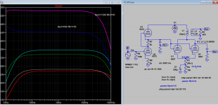
Yes I see that the grid can't swing as far when the plate inductance is very high, distortion set in well below 20V.
Here SRPP stage included (gain=20) and 2 primary inductance are used for comparison. Highest gain is about 55 when pri inductance is 110H and Rk1 50 ohms.
Attachments
I like transformer coupling and will second Pieter's comment about great designs on the web, the M10 is not one of them.
Yeah, there's a lot of back and forth here when it doesn't take any calculations to see that the ratio of that transformer is wacky, even for just one section of 5687. I'm pretty sure there are at least 3 Lundahl transformers that would work better than what's drawn up in that design.
Thanks Koonw!
.....
Could you sim the complete output stage and see what happens?
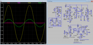
Here is sim included the riaa unit, psu not included. Some values are adjusted maybe to tube model in use. Those interested can sim PSU as an exercise.
* Data extracted 16 June 2005
* from ElectroHarmonix 6072A/12AY7EH tube
*
.SUBCKT 6072 A G K
+ PARAMS: EX=1.18296637295072 MU=41.7794590897682 KG1=1283.6566442837 KP=328.825557514402 KVB=2847.72219152647
+ Go=0.34371558686874 KG=0.000213922190232166 AG=0.874211243853364 BG=0
+ CCG=1.3P CGP=1.3P CCP=0.6P
E1 4 0 VALUE={V(A,K)/KP*LN(1+EXP(KP*(1/MU+(V(G,K)-Go)/SQRT(KVB+V(A,K)*V(A,K)))))}
G1 A K VALUE={ (PWR(V(4),EX)+PWRS(V(4), EX))/(KG1) }
RCP A K 1G
G2 G K VALUE = {IF(V(G,K)>0,{Kg}*((({Ag}+V(A,K))/({Bg}+V(A,K)))**4)*V(G,K)**1.5,0)}
C1 G K {CCG} ; CATHODE GRID
C2 G A {CGP} ; GRID-PLATE
C3 A K {CCP} ; CATHODE-PLATE
.ENDS 12AY7
Attachments
Thanks Koonw!
As I see it now, the output stage (that is 6072 SRPP cascaded into 5687) before the output transformer has a gain of 20 x 5.6 = 112. 5.6 is your simmed 1.31V x 4.26 (winding ratio of 60H:3.3H = 4.26).
With the 33:1 winding ratio as per Audio Note's specification, with 1V input of the complete output stage, the output voltage will be 112:33 = some 3.4 V. Actually a bit higher because the gain of the 5687 will be higher with the higher load impedance presented by the 33:1 transformer.
Critical point remains the grid voltage of the 5687; the tube will distort with 20V on its grids.
Besides it will not be able to produce an anode voltage of 112V.
So IMO the output stage design has serious weaknesses.
Could you sim the complete output stage and see what happens?
Why do you insist on using the wrong step down ratio?!
Not I don't insist, the source is attached you can do whatever you want to make it fit. If someone or yourself happen to have sim correctly please share it.
Thanks for sharing your simulations, but please bear in mind that not many people are interested in SPICE simulations, so posting screen shots of your simulations could lead to confusion for some readers, as they do not reflect the actual circuit being discussed. If you are trying to improve or modify the circuit, then say so.
Thanks for sharing your simulations, but please bear in mind that not many people are interested in SPICE simulations, so posting screen shots of your simulations could lead to confusion for some readers, as they do not reflect the actual circuit being discussed. If you are trying to improve or modify the circuit, then say so.
The sim is to be able to verify things only when the input data is correct or accurate. Now this is not the case but we have to accept what assumptions and verify that with actual circuit. No fool will accept any sim without verification.
Now to use step down ratio of 33:1, we assume that the pri inductance is 110H, and sec inductance is 0.1H, correct? so here go the sim (hope it does not hurt any one feeling), a sim is sim.
Attachments
You'd be surprised...No fool will accept any sim without verification.
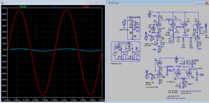
Anyway, please remember that just a few of the users even bother with running simulations, so the majority of the users can not verify anything even if you provide the simulation files, instead they can only rely on whatever content are shown in the screenshots. That said, thanks for re-running the simulation.Some people have asked with is the output impedance of M10 twin 5687 output stage, here is sim result. The dip in impedance in bottom end may explain the lack of bottom end freq response. This is overall output impedance for T=33:1 step down transformer reflected impedance and tubes output impedance.
Attachments
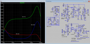
Some people have asked with is the output impedance of M10 twin 5687 output stage, here is sim result. The dip in impedance in bottom end may explain the lack of bottom end freq response. This is overall output impedance for T=33:1 step down transformer reflected impedance and tubes output impedance.
I am not able to make much of this
What is the output impedance of this thing measured at the output?
- Status
- This old topic is closed. If you want to reopen this topic, contact a moderator using the "Report Post" button.
- Home
- Amplifiers
- Tubes / Valves
- Audio Note M10 Clone