Hi
I will take this last messages from a thread :
How much PS capacitance for PP output stage?
Quote:
Originally Posted by waltube
No, in my opinion, because the bypass ( intended as pp, high quality) acting as an ideal cap for the frequency where the big caps can have a L
DF96:Your opinion is wrong. Maybe you are forgetting that inductive reactance and capacitive reactance have opposite signs so in parallel they increase impedance?
Quote:
Every one of you knows the meanings of bypass.
DF96:I know the meaning of bypass and what it does. Rayma does too. I am not certain that you understand it.
And I will send some test maybe can help to understand something on caps.
The test set was:
AP1 + Rhode ans Schwarz APN62 + Pico scope
the caps are: 150 uF -350 vdc - 470uF 400vdc - 1500 uF 400vdc and 0,48 uF 400vdc pp
in attach some picture.
The forst is a equivalent circuit of the cap. Rs is a resistance (normally small) related to lead or anodes and Ls also related to lead.
I omitted the R related to the dielectric because it is very high.
C is the capacitor under test.
While Rs is a fix value the Ls change with frequencies
The second circuit is the test circuit where i send the signal to the cap in series there is a 1k2 Holco resistor where I monitor the output signal.
From Ap1 the signal is 1 volt start from 10 hz to 200 Khz, with Rhode and Schwarz go up to 250 khz.
In theory the signal on the output must be the same of input; the 1k2 resistor from Holco is perfect for this purpose because has no parasitic.
All the caps under test are of a very good quality
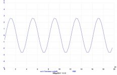
1- the freq. answer of a 150 uF 350 vdc 105°c Panasonic, there are two curves similar , one only the 150 and the other with a bypass of 0,47 uf 400vdc PP. No attenuation on both curves ( the little one is tipycal of AP1)
2- same test with 470 uF 400 vdc 105°C Elna; same results
3- same with 1500 uF 400 vdc Sic Safco ( very good stff and expensive), same results.
4- a FFT of the 1500 uF with and without 0,47, just for info
5- a 1Khz got at the out of the 1500 uF
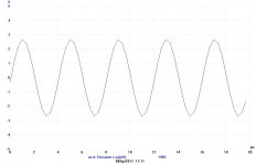
6- the 250 KHz from 1500 uF + 0,47 uF
7- the signal directly from R&S on 1k2 resistor, the value read is similar as 6
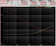
In addition two diagram comes from a very smart sw + little hw developped by fabrizio Montanucci (tech director on Audioreview magazine) where is posiible to see the difference from a normal NP electrolitic cap and a good PP
8- electr. NP , the modulus ig good until the 10 KHz the is changing not in relation theory, on the little window on top is possible to see the valueof Z vs freq..
It is also possible to see the phase tha is changin and is not costant
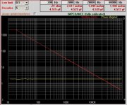
9-the same test with a good PP; the phase is quite perfect as the modulus of impedance.
For the moment I stop here.
Ciao
Walter
I will take this last messages from a thread :
How much PS capacitance for PP output stage?
Quote:
Originally Posted by waltube
No, in my opinion, because the bypass ( intended as pp, high quality) acting as an ideal cap for the frequency where the big caps can have a L
DF96:Your opinion is wrong. Maybe you are forgetting that inductive reactance and capacitive reactance have opposite signs so in parallel they increase impedance?
Quote:
Every one of you knows the meanings of bypass.
DF96:I know the meaning of bypass and what it does. Rayma does too. I am not certain that you understand it.
And I will send some test maybe can help to understand something on caps.
The test set was:
AP1 + Rhode ans Schwarz APN62 + Pico scope
the caps are: 150 uF -350 vdc - 470uF 400vdc - 1500 uF 400vdc and 0,48 uF 400vdc pp
in attach some picture.
The forst is a equivalent circuit of the cap. Rs is a resistance (normally small) related to lead or anodes and Ls also related to lead.
I omitted the R related to the dielectric because it is very high.
C is the capacitor under test.
While Rs is a fix value the Ls change with frequencies
The second circuit is the test circuit where i send the signal to the cap in series there is a 1k2 Holco resistor where I monitor the output signal.
From Ap1 the signal is 1 volt start from 10 hz to 200 Khz, with Rhode and Schwarz go up to 250 khz.
In theory the signal on the output must be the same of input; the 1k2 resistor from Holco is perfect for this purpose because has no parasitic.
All the caps under test are of a very good quality
1- the freq. answer of a 150 uF 350 vdc 105°c Panasonic, there are two curves similar , one only the 150 and the other with a bypass of 0,47 uf 400vdc PP. No attenuation on both curves ( the little one is tipycal of AP1)
2- same test with 470 uF 400 vdc 105°C Elna; same results
3- same with 1500 uF 400 vdc Sic Safco ( very good stff and expensive), same results.
4- a FFT of the 1500 uF with and without 0,47, just for info
5- a 1Khz got at the out of the 1500 uF
6- the 250 KHz from 1500 uF + 0,47 uF
7- the signal directly from R&S on 1k2 resistor, the value read is similar as 6
In addition two diagram comes from a very smart sw + little hw developped by fabrizio Montanucci (tech director on Audioreview magazine) where is posiible to see the difference from a normal NP electrolitic cap and a good PP
8- electr. NP , the modulus ig good until the 10 KHz the is changing not in relation theory, on the little window on top is possible to see the valueof Z vs freq..
It is also possible to see the phase tha is changin and is not costant
9-the same test with a good PP; the phase is quite perfect as the modulus of impedance.
For the moment I stop here.
Ciao
Walter
Attachments
-
caps test.bmp87.9 KB · Views: 37
-
1-150_350+047.pdf12.5 KB · Views: 41
-
2-470_400+047.pdf12.5 KB · Views: 33
-
3-1500_400+047.pdf12.5 KB · Views: 32
-
4-FFT_1500+047.pdf16.6 KB · Views: 38
-
5-1v_1KHz_1500.bmp124.6 KB · Views: 29
-
 6-2vout_250KHz_1500_400vdc.jpg35.6 KB · Views: 203
 -
 7-2vout_250KHz_R&S.jpg97.9 KB · Views: 210
 -
 8-elettroliticoNP.jpg121.5 KB · Views: 211
 -
 MKP.jpg120.3 KB · Views: 207
With a scale from +3dB to -7dB the frequency response plots seem designed to hide any effect. However, if the two plots are very similar then that would not only demonstrate that the bypass does no harm but also that it does no good. In 'proving' that I am wrong you have also 'proved' that you are wrong too!
Let's do some sums and bring some light into this topic.
Start with a main cap of 150uF. Assume series inductance of 100nH, and ESR of 0.2R. If this cap is used as a coupling cap with 1.2k load (i.e. a high pass filter) then the LF rolloff will be at 0.88Hz so fine (or even too low?) for audio. The cap will have its own series resonance at 41kHz. However, this will be quite a broad resonance due to ESR. The LF and HF corners of the central flat impedance region will be at around 5.3kHz and 318kHz (about 8 times lower and 8 times higher than the resonance point). This cap is obviously good for audio use as it stands. It doesn't need a bypass.
However, let us suppose that someone who doesn't understand that adds a bypass of 0.47uF. The first thing to say is that over the audio range this will make no difference, as the bypass is only 1/319 of the main capacitor value. At low audio frequencies it increases the capacitance by 0.3% - well within electrolytic tolerance. We have already seen that at the higher audio frequencies the main cap looks like a 0.2R resistor from around 5.3kHz to 218kHz. A 0.47uF cap in parallel with 0.2R only has a significant effect from around 1.7MHz upwards. So no useful effect within the audio band or the low RF band.
However, it is slightly worse than that. From 41kHz the main cap is looking increasingly inductive, although by only a small amount until above 318kHz. 0.47uF will resonate with 100nH at 734kHz. Because of ESR this will be a low Q resonance - only about 2.3. Well above this the bypass cap will start to have a useful effect.
So, to sum up:
150uF is fine for audio with no bypass
150uF plus 0.47uF bypass is the same as no bypass for audio purposes and you would find it hard to distinguish between them - so the bypass does no good for audio
150uF plus 0.47uF bypass is worse than no bypass in a frequency region from about 300kHz to around 1MHz - so the bypass does no good for low RF
150uF plus 0.47uF bypass is better than no bypass for the rest of the RF region - but in the lower part of that region 0.47uF on its own would be better.
You see how thinking can not only explain measurements but also, in many cases, replace measurements?
Your comments haven't any technical facts replicable.
These tests are clear and replicable everywhere, in addition there aren't any type of words that can replace the practical test. They must be run together
With the words you can explain the test, if you are able, of course.
Walter
These tests are clear and replicable everywhere, in addition there aren't any type of words that can replace the practical test. They must be run together
With the words you can explain the test, if you are able, of course.
Walter
I can do this in next weeks; I am moving.
In every case the test set results show the good quality of the cap used.
One practical example
if you read the Z of cap on point 8 at 80 KHz and the one of nr. 9 at the same frequency, one is 0,518 ohm and the other is 1,992 millihom.
If I put them in parallel which is the Z at that frequency?
This is what I am trying to explain.
In this case we are sure that for a circuit this parallel is almost a short for an ac signal, or not?
Walter
note: it is curious that nobody ask info for this sw; it is very smart and soon will be available when Fabrizio complete the tests; there is alslo a little hw because the software( with a good sound card) is able to define the parasitic on contacts and wires that connect the Dut and it will subtract these bad info so the measurement is effectively the components we have.
Last edited:
Somewhere between 1.984m and 2.000m, depending on the phase angle between their impedances.waltube said:One practical example
if you read the Z of cap on point 8 at 80 KHz and the one of nr. 9 at the same frequency, one is 0,518 ohm and the other is 1,992 millihom.
If I put them in parallel which is the Z at that frequency?
Arithmetic. Where do your numbers come from? I simply combined the two impedances, but not knowing their relative phase I simply assumed the two opposite cases. The actual answer lies somewhere between these two.waltube said:You number are comes from?
Put an inductance in parallel with a capacitance and you can be absolutely sure that the impedance will be greater than either of them. Note I said "inductance" and "capacitance", not 'inductor' and 'capacitor' - there is a difference. From 10's of kHz up some larger capacitors provide inductance to the circuit, not capacitance.Is not possible, in every case, that the Ztot will more than 1,992 millihom and this is sure!
Which are the two opposite case? for me is not clear what you are saying.
Then, in a capacitor the Ls is in series with C (and Rs); I told you in the past!
This is the equivelent circuit known to all of us.
So I confirm that the Ztot can't be more than 1,992 millihom
I show you that on large caps ( what you mean large? ) if it is good the Ls reasonable low until at 250 kHz; I haven't a generator that goes up, unfortunately.
Walter
- Status
- This old topic is closed. If you want to reopen this topic, contact a moderator using the "Report Post" button.
- Home
- Amplifiers
- Tubes / Valves
- caps and test