I've been playing a bit with LTSPICE as I'm still trying to work out what matters and what doesn't (at least from a measurements point of view).
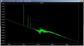
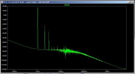
The schematic I was experimenting on is using 6L6GC output tubes in PP UL Class A. According to the specs (if I'm reading them right) the impedance should be about 5k. Out of curiosity I tried a 10k/8 tranny instead of the 5k/8 I had been using and saw a big improvement in the low frequency noise floor.
Are there any reasons why I might not want to use the higher impedance tranny if the simulated results are better? I presume the tube specs are given as they are for a reason...
The difference in simulated output power is less than 10%.
Attachments
Here we go...
I can't simulate. Need to have transformer symbols (ULPPTran5000 and ...10000)
I can't simulate. Need to have transformer symbols (ULPPTran5000 and ...10000)
Sorry, I thought they'd been pulled into the .asc.
Attachments
I take back what I said yesterday about the ultra low current, I must have been having a bad day. 
I can now see there are issues with the splitter, and I'm not sure how to fix it. Now that I'm more current aware (!) it is obvious that altering the anode resistors between the two sides can help balance either the voltage or the current, but of course that means that the other is quite a bit out of whack and I don't know which is more important or what to do about it. I'm sure they're supposed to be better balanced than they are in this case.
I'm re-posting the files as well, hopefully there aren't the help-unfriendly issues I had with those from yesterday. Sorry about that.
Attachments
I've been playing a bit with LTSPICE as I'm still trying to work out what matters and what doesn't (at least from a measurements point of view).
The schematic I was experimenting on is using 6L6GC output tubes in PP UL Class A. According to the specs (if I'm reading them right) the impedance should be about 5k. Out of curiosity I tried a 10k/8 tranny instead of the 5k/8 I had been using and saw a big improvement in the low frequency noise floor.
Are there any reasons why I might not want to use the higher impedance tranny if the simulated results are better? I presume the tube specs are given as they are for a reason...
The difference in simulated output power is less than 10%.
In general, higher Z OPT gives stronger self-feedback, better DF, lower Pout. It makes sense with (noFB) triodes.
But with tetra-penta you are aiming for higher Pout+efficiency anyway, and likely you will have strong global FB´s somewhere..
Therefore higher Z is against you goals (squeezing most W possible, beat the crap out of it
)- Status
- This old topic is closed. If you want to reopen this topic, contact a moderator using the "Report Post" button.
- Home
- Amplifiers
- Tubes / Valves
- Another newbie output transformer question