I built a version with four 6CG7 (300v B+) and didn't like it. Too tubey, slow bass. Changed it over to four 6DJ8 (150v B+) and liked it much more. See link to WoS article on Aikido 12Vac using 6DJ8s. Battle of the Cheap Line Stages – Part 1 | Wall of Sound | Audio and Music Reviews
Cheers, Steve
Cheers, Steve
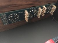
glassware front panel board
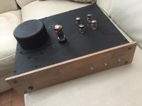
Almost done assembling the aikido all in one with ps tube ,just waiting for some rca and a power switch to show up . coming from china might have to wait awhile .Thinking of installing some leds on the rotary switch to show what input its on any ideas ?
Almost done assembling the aikido all in one with ps tube ,just waiting for some rca and a power switch to show up . coming from china might have to wait awhile .Thinking of installing some leds on the rotary switch to show what input its on any ideas ?
Attachments
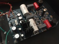
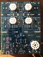
Well the parts finally arrived . I will never order Chinese delivery again. better off staying with digi-key or mouser .I've decided to go with 6cg7 input and 6N23P-EV reflektor for output tubes also a 5u4gb for rectifier and a hammond pt 270ex . I don,t have a variac to slowly power it up so I want to be sure everththing is correct. Has anyone built this version of the aikido all in one kit , is there any incorrect info in the manual . any help would be great.
Attachments
{snip}.... I don,t have a variac to slowly power it up....
Lamp Limiter!
You're complaining about waiting a month? You're lucky as I regularly wait up to 4 months!
I've built the circuit, not the kit but it was smooth sailing. If you are nervous you can connect the primary in series with a 100W light bulb. If there's a problem the light will glow bright.
I've built the circuit, not the kit but it was smooth sailing. If you are nervous you can connect the primary in series with a 100W light bulb. If there's a problem the light will glow bright.
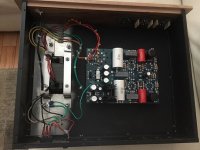
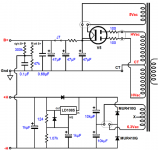
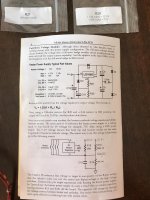
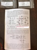
I have question about the heater power supply section ,if I,am looking at this correct there seems to be some confusion in parts placement of the regulator adjustment r21,and r20 here is what i have. The image is my pcb which from the trace looks like r20 goes into the adjust on the regulator rather than r21. The second image is my user guide schematic , the third image I found on tcj site for this pcb . I think the pcb is not marked correctly. any help would be great thanks.
Attachments
A few thoughts
Other than the hum does the amp work OK? I haven't built this board but I have built several other Aikidos.
One of your pictures from earlier shows that the inputs aren't connected, are they now?
All of the frames of the switches (attenuator, input select) should be connected to ground to prevent hum pickup. Try disconnecting the attenuator leads from the board then solder short pieces of wire across the board input points.
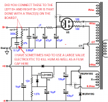
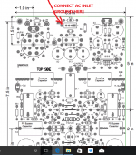
I don't think the ground from the power inlet is connected to the right place on the board. Shouldn't it be connected to HOUSE GND term near back of board?
Once a buddy couldn't get rid of hum until he connected an electrolytic cap across the film cap in the ground ref circuit, see attachment.
I've corrected one of your manual pictures as well, see attachment.
Steve
Other than the hum does the amp work OK? I haven't built this board but I have built several other Aikidos.
One of your pictures from earlier shows that the inputs aren't connected, are they now?
All of the frames of the switches (attenuator, input select) should be connected to ground to prevent hum pickup. Try disconnecting the attenuator leads from the board then solder short pieces of wire across the board input points.
I don't think the ground from the power inlet is connected to the right place on the board. Shouldn't it be connected to HOUSE GND term near back of board?
Once a buddy couldn't get rid of hum until he connected an electrolytic cap across the film cap in the ground ref circuit, see attachment.
I've corrected one of your manual pictures as well, see attachment.
Steve
Attachments
- Status
- This old topic is closed. If you want to reopen this topic, contact a moderator using the "Report Post" button.
- Home
- Amplifiers
- Tubes / Valves
- Aikido all in one with ps tube build