To increase bass : turn bass control up !
No such thing on my system, except perhaps software EQ, which I'm doing already. Many tube reviewers state they get deeper bass with such and such tube, but I realize this is very much in relationship with the amp they're using. I'll get the JJ KT77 and see what this brings
") .
. Threads merged.
fb2017,
I came onto your thread late. Now I finally read through all of the posts in this thread. It is curious that nobody ever attempted to answer in regard to your scope screen shots, the ringing at the start, and the large reduction of ringing over time.
You probably do not need much power to drive those Fostex horn loaded speakers, and most of the time you are in class A (neither output tube in cut off).
I have used paraphrase splitters, and they sounded OK. But I prefer splitters that have a current source in the coupled cathodes. This almost always requires a negative supply, or has to be dealt with another way, when the input stage is the splitter (that is another subject for another thread). The cathode splitter has 6 dB less gain, and the open loop to closed loop ration is 6 dB less. Keep the splitter you have.
A good feature you have is the individual bias resistors and bypass caps for each output tube. Use matched pairs if you replace tubes, you do not have to have a matched quad. Just match the left pair; and just match the right pair.
If you want to, do put a 1 Ohm resistor for each tube, between the bottoms of the self bias resistor/bypass cap networks, and ground. You can try this for just the right or just the left channel to see the effect. Use your scope to see when you go out of class A. You might need to use 10 Ohm resistors, in order to see the signal better on your scope. You could do this when the amp is loaded with an 8 Ohm load. But when you really should do it, is when you are listening to music, at the volume you like, when the amp is connected to your loudspeakers.
If you want to try another thing, remove the output transformer screen tap wires, and insulate them. Then connect 4 100 Ohm resistors, one each from the output tube's plate to the output tube's screen. You can even just do it to one channel and compare to the other channel (2 resistors). This is triode wired mode. The maximum output power will go down, and depending on the negative feedback and loop gain, the gain may go down. But the damping factor, and the nature of the distortion will probably change.
The impression of Bass can also vary as the damping factor varies.
Continue to enjoy listening to the amp and speakers.
Hi, thank you for your very helpful post. There are a lot of very interesting ideas in here, and it gives me something to do . I haven't measured the amp in one year, I presume the ringing would be gone by now. Anyway, I am usually listening to low volumes (around 1-3W of output power), the Fostex being as efficient as they are, and I really love what I'm hearing. It is so stronlgy holographic that the speakers completely dissapear, and the soundstage move meters behind the wall. All of my friends that visited and listened to the system were quite impressed as well. I am also offering listening experiences to anyone wanting to give it a go (and wishes to travel to Germany, Lower Saxony for this ). Your 1 Ohm resistor idea, you mean between let's say C103 C104 and ground? It is unfortunately a bit difficult to implement properly, as it is not a point to point construction, but PCB. Yes, using the EL34 in triode mode was a possibility that crossed my mind. As with my speakers I'm never needing more than 10W, there is even the possibility of converting this particular amp to an 300B SET one, of about 8 Watt, that should be more than enough. Audion even added the additional filter circuit traces on the PCB for this, they sit unused in my amp. Ron Clark, the designer of the Dallas II also recommended a 1-4 Ohm resistor in the series with the speaker for enhancing the transmission line effect (by raising the speaker's Q), that would improve the bass as well.
. I haven't measured the amp in one year, I presume the ringing would be gone by now. Anyway, I am usually listening to low volumes (around 1-3W of output power), the Fostex being as efficient as they are, and I really love what I'm hearing. It is so stronlgy holographic that the speakers completely dissapear, and the soundstage move meters behind the wall. All of my friends that visited and listened to the system were quite impressed as well. I am also offering listening experiences to anyone wanting to give it a go (and wishes to travel to Germany, Lower Saxony for this ). Your 1 Ohm resistor idea, you mean between let's say C103 C104 and ground? It is unfortunately a bit difficult to implement properly, as it is not a point to point construction, but PCB. Yes, using the EL34 in triode mode was a possibility that crossed my mind. As with my speakers I'm never needing more than 10W, there is even the possibility of converting this particular amp to an 300B SET one, of about 8 Watt, that should be more than enough. Audion even added the additional filter circuit traces on the PCB for this, they sit unused in my amp. Ron Clark, the designer of the Dallas II also recommended a 1-4 Ohm resistor in the series with the speaker for enhancing the transmission line effect (by raising the speaker's Q), that would improve the bass as well.fb2017,
From your schematics in Posts #15 and #40,
Lets work on one channel at a time . . .
I expect that all the parts are mounted on the PCB.
Look at the schematic, and then at the PCB.
1. Take the negative lead of C103 out of the PCB (it is connected to ground/common) Take the end of R130 that is also connected to ground/common out of the PCB (not the end that connects to C103 positive and EL34 Cathode.
Connect the new loose ends of C103 and R130 together. Connect a 10 Ohm resistor from that new junction of C103 and R130, and the other end of the 10 Ohm resistor to the PCB where either C103 or R130 was pulled out (ground/common). That is your current sense resistor for V101. Connect scope probe ground clip to the ground/common end of the 10 Ohm resistor, and the scope probe hot tip to the other end of the 10 Ohm resistor. You can also measure the DC current of V101, with your DMM across the 10 Ohm resistor. DC Volts/10 Ohms = Amps
2. Repeat for C104 and R130, and V102. Now you can compare the current in one 10 Ohm and the other 10 Ohm, and see where you are in class A, and at what volume you are in class AB.
That is one channel.
The other channel: 3. Repeat R231 C203 V201 R230 C204 V202 Again, test DC current with a DMM, and Class A / Class AB with a scope.
Now, for Triode wiring:
Look at the schematic again.
One channel: Remove the ultra linear tap from the transformer at J106 Insulate the ultra linear tap wire Jumper J105 and J106
Remove the ultra linear tap from the transformer at J108 Insulate the ultra linear tap wire Jumper J108 and J109
(The screens already have resistors R153 and R154 on the circuit board)
The other channel: Remove the ultra linear tap from the transformer at J206 Insulate the ultra linear tap wire Jumper J205 and J206
Remove the ultra linear tap from the transformer at J208 Insulate the ultra linear tap wire Jumper J208 and J209
(The screens already have resistors R253 and R254 on the circuit board)
Triode wiring only one channel will not help you to compare, unless you have a balance control, I expect the triode wired channel might have as little as 1/2 the gain (6dB less gain), but that depends on the gain without negative feedback versus gain with negative feedback. If the open loop gain (no NFB) to closed loop gain (NFB) ratio is high enough, there will be no gain loss when triode wired.
I have purchased a pair of secondhand OPTs from Audion, as used on the Silver Knight MKII. I looked through the documentation supplied with them, and apart from the application in the Silver Knight amplifiers, it appears the same OPTs are supplied with the Edison 60 kit (also from Audion). Hence the post here.
According to the notes about strapping the primary windings, the transformers can be used for both SE amps and Push Pull. I knew that an SE OPT has to have an air gap to restrict the flow of DC to prevent saturation, so assumed that an SE OPT would only be used for SE applications.
Is it so that an SE OPT works well for PP? If so, these OPTs should give me a lot of flexibility in their use. They have 4 primary windings, and a UL tap is one possible combination.
What is this stage doing?
I have read through this thread, and it seemed like fb2017 got a bit of a raw deal at the start, since there were some quite negative comments about the topology of the design.
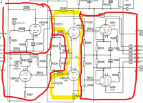
I'm still finding my way with tube circuits, and I was struggling to make sense of the design. The part I was confused over were the cathode coupled driver tubes, ringed in yellow below.
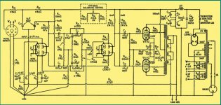
The circuit reminded me of the GEC 50W amplifier, and examining that more closely I think it is identical. So then I looked at the write up of the GEC amp on The Valve Museum, and I have saved an expert's response here, because now I can see the justification for the topology.
From the valve museum ...
The use of a push-pull pair of triodes for the driver stage was chosen so that the output stage would be symmetrically driven, and that no unbalanced operation would occur even at the onset of grid current in the output valves during overload. The removal of the phase splitter to an earlier stage ensures that the time constants in the grid circuits of the output valves are the same. The B329 is used in this stage because it has a low anode impedance, about 10,000 Ohms. With this low value of driver impedance the phase shift due to the input capacity of the output stage is relegated to frequencies above 50 kHz, and this, combined with the symmetry of the circuit, greatly assists in ensuring freedom from HF instability when feedback is applied overall.
Design for a 50 Watt Amplifier
The article does suggest that there should be some mechanism to balance the driver stage, for the best hifi solution.
The phase splitter is a floating paraphase, and that got a lot of abuse at the start of this thread as being 'old fashioned', but it is just another way to skin a cat, isn't it?
Is the Edison 60 a sound schematic, that is a good build candidate for 2020? Or is the design dated because it is tackling the problem in an archaic way, and hence it is not a good solution? Could it be that the design is good, but more suited to tubes that are hard to drive?
I have read through this thread, and it seemed like fb2017 got a bit of a raw deal at the start, since there were some quite negative comments about the topology of the design.
I'm still finding my way with tube circuits, and I was struggling to make sense of the design. The part I was confused over were the cathode coupled driver tubes, ringed in yellow below.
The circuit reminded me of the GEC 50W amplifier, and examining that more closely I think it is identical. So then I looked at the write up of the GEC amp on The Valve Museum, and I have saved an expert's response here, because now I can see the justification for the topology.
From the valve museum ...
The use of a push-pull pair of triodes for the driver stage was chosen so that the output stage would be symmetrically driven, and that no unbalanced operation would occur even at the onset of grid current in the output valves during overload. The removal of the phase splitter to an earlier stage ensures that the time constants in the grid circuits of the output valves are the same. The B329 is used in this stage because it has a low anode impedance, about 10,000 Ohms. With this low value of driver impedance the phase shift due to the input capacity of the output stage is relegated to frequencies above 50 kHz, and this, combined with the symmetry of the circuit, greatly assists in ensuring freedom from HF instability when feedback is applied overall.
Design for a 50 Watt Amplifier
The article does suggest that there should be some mechanism to balance the driver stage, for the best hifi solution.
The phase splitter is a floating paraphase, and that got a lot of abuse at the start of this thread as being 'old fashioned', but it is just another way to skin a cat, isn't it?
Is the Edison 60 a sound schematic, that is a good build candidate for 2020? Or is the design dated because it is tackling the problem in an archaic way, and hence it is not a good solution? Could it be that the design is good, but more suited to tubes that are hard to drive?
Attachments
fb2017,
back to your original scope traces, I'am not sure why the waveform after 2 mins should have a slope which then disappears. What I would say that the ringing indicates that the amp is a little close to HF instability. I think the culprit is the negative feedback. I would suggest you try a small cap across the feedback resistor R113/R213 from the output transformer to the input stage.
Hope this is useful.
Basically this amp sounds so good as it is that I'm not interested in changing anything. I'm now using it with Gold Lion KT77s, they are certainly better than the original Electroharmonix EL34 (especially in the bass). My intention was to erase this thread altogether after the bashing from people who never post any builds of themselves happened, but as that wasn't possible it's still here for all to enjoy.
I'm not sure what "Is it a good candidate for 2020" means? You can get an extraordinary good kit, with some esoteric parts if that's your hobby, for not too much money, that sounds just as good in 2020 as it did in 2017 (in my case).
Its disappointing when that happens. If you put your amp on display and ask for comments that what you got! Many of them are good suggestions which others have spent time on. I find it better to ask a question when you have an issue. The ringing on the square wave I would look into. I have built both SS and valve amps from scratch.
I have read through this thread, and it seemed like fb2017 got a bit of a raw deal at the start, since there were some quite negative comments about the topology of the design.
I'm still finding my way with tube circuits, and I was struggling to make sense of the design. The part I was confused over were the cathode coupled driver tubes, ringed in yellow below.
The circuit reminded me of the GEC 50W amplifier, and examining that more closely I think it is identical. So then I looked at the write up of the GEC amp on The Valve Museum, and I have saved an expert's response here, because now I can see the justification for the topology.
From the valve museum ...
The use of a push-pull pair of triodes for the driver stage was chosen so that the output stage would be symmetrically driven, and that no unbalanced operation would occur even at the onset of grid current in the output valves during overload. The removal of the phase splitter to an earlier stage ensures that the time constants in the grid circuits of the output valves are the same. The B329 is used in this stage because it has a low anode impedance, about 10,000 Ohms. With this low value of driver impedance the phase shift due to the input capacity of the output stage is relegated to frequencies above 50 kHz, and this, combined with the symmetry of the circuit, greatly assists in ensuring freedom from HF instability when feedback is applied overall.
Design for a 50 Watt Amplifier
The article does suggest that there should be some mechanism to balance the driver stage, for the best hifi solution.
The phase splitter is a floating paraphase, and that got a lot of abuse at the start of this thread as being 'old fashioned', but it is just another way to skin a cat, isn't it?
Is the Edison 60 a sound schematic, that is a good build candidate for 2020? Or is the design dated because it is tackling the problem in an archaic way, and hence it is not a good solution? Could it be that the design is good, but more suited to tubes that are hard to drive?
Just bumping my post #49 above. I had no replies.
The original poster got quite a lot of grief for the schematic of this kit, with the implication it was a primitive design, and not worthy of being built today.
The schema is basically the same as the GEC 50W amplifier, and gets discussed alongside other classic designs.
I'm starting to think about my next build, which will be a classic design, and since I have a pair of OPTs from the same kit, I was considering this design as a starting point. Another option is the Brimar 25P1 (simpler design with pentode gain, double triode LTP phase splitter, KT66 equivalents output).
I have an old PA case from the 50's, with a nice cage. Chassis size is 21cm x 42cm.
If your question is about the OPTs, obviously the Silver Night ones are of extremely high quality, probably the best in class. And I can tell you, the OPTs are defining 90% of your sound.
I would like to suggest you to build the SE variant of the kit I have, if you want to experiment with SE. Otherwise just buy the kit and build the push-pull Class A amp I have.
If you worry about the sound quality - in the dual monoblock variant I have made (fully separated power sources), and with the Dallas II horns, it gives me plenty of jawdropping moments. Recently I am listening to a lot of classic (think YoYoMa's recent high resolution recordings of Bach's cello suites, or Mozart concerts for strings or wind instruments. Another album that impressed me was Taylor Swift's Reputation - the bass is extremely tight and well defined. I'm not sure how some people can think they have the right of an opinion on this schematic without hearing the actual amp at work, so that's that... Like I said, the 50W Silver Night OPTs will absolutely define your sound.
Just bumping my post #49 above. I had no replies.
The original poster got quite a lot of grief for the schematic of this kit, with the implication it was a primitive design, and not worthy of being built today.
The schema is basically the same as the GEC 50W amplifier, and gets discussed alongside other classic designs.
I'm starting to think about my next build, which will be a classic design, and since I have a pair of OPTs from the same kit, I was considering this design as a starting point. Another option is the Brimar 25P1 (simpler design with pentode gain, double triode LTP phase splitter, KT66 equivalents output).
I have an old PA case from the 50's, with a nice cage. Chassis size is 21cm x 42cm.
It makes me happy to read your build report about the amplifier and I have a small story about it. This was my first build many, many!, years ago. By a chance I happen to meet the designer who happen to live in southern part of Stockholm (still does) at the time. His name is found on the schematics, Erik Andersson, famous for other amplifier designs as well. He worked together with David Chessel and designed the Audion at the time. Anyhow I met him at my work and we started talking about his affection for motorcycle and he told me he was working with tube amplifiers and had a small workshop in his home. He invited me to his home and demonstrated this amplifier and I was so impressed that I bought a kit directly from him. Ended up making a misstake because i misunderstood something in the schematic and had to pay him a visit to get it fixt but after that the amplifier sounded amazing and I used it for many years. I returned to Erik many times and bought also other kits from him, the 300B and so on. I have a deep respect for Erik and his designs and perhaps mostly because of the amazing sound from a relatively simple looking design. I have built many amplifiers since then but I'm not a superexpert but do not think it is outdated. I much regret that I sold my Edisson 60 and would love to build one again. The fact that it is still available speaks for itself. Also interesting that you now run kt77 instead of the EL34. Thanks for your original post!
> What is this stage doing?
It's a gain stage. We have a beastly Power Stage, a delicate Input/NFB Stage, and for these tube types we really want one more stage.
> bumping my post #49 above. I had no replies.
I thought you replied-yourself admirably.
Paraphase gets no respect because it is out of fashion. Engineering is NOT pure logic. Designers go with what tickles their fancy. NON-designers echo garbles of what they think they read/heard somewhere.
Considering the expected imperfect balance across the output pair(s), I would not fret about driver balance. I have had totally-trimmable amplifiers and did not think they sounded better than amps built with 20% tube and 5% resistor tolerance.
Considering the expected imperfect balance across the output pair(s), I would not fret about driver balance.
Do you refer here to the Auto-Bias?
Also interesting that you now run kt77 instead of the EL34. Thanks for your original post!
You're welcome! Your story is also very interesting, I would have loved to meet the designer as well. Indeed, the KT77 is a drop in replacement for the EL34 in this amp, and they work perfectly. Due to its conversion to 100V, the bias and maximum power output is slightly lower now on mine, but that hasn't affected the quality a bit...
Hi
This seems to be the thread to discuss the Edison 60, so I'm going to join the fun.
I picked up a semi-completed kit a few months ago and finished the build a few weeks ago, mine seems to have most options; double PTs, the extra power supply caps, alps blue pot, better connectors etc. I was missing the correct build manual and the top lid, and Edison were very helpful.
Anyway, what I am a little annoyed by is the hum level, it is a tad higher than I would like so I would like to hear your impressions on your amps.
Basically it hums (50 & 100hz harmonics) a little bit, you hear it most when it is turned off, but it's there. I have gone through the instructions carefully, and the one thing I haven't done is use the two 22ohm resistor to elevate the potential of the signal boards. The instrauction seems slightly unclear on that - it would seem to me to be either useless, since the audio boards are grounded together through the colume pot, or would introduce ground hum... I'll probably test it anyway since I'm chasing hum.
I'm currently running ultralinear push-pull mode btw, it was set up as triode when I got it, and the hum was similar, but the triode mode sounded a little sweeter. Will need to try it again... I'm using DIY two way monitors with Accuton drivers (1" and 7"), so they're certainly not super efficient.
- Status
- This old topic is closed. If you want to reopen this topic, contact a moderator using the "Report Post" button.
- Home
- Amplifiers
- Tubes / Valves
- Audion Edison 60 building and using report