Hi!
Seems about right. You can increase the 200k grid resistor. The 71A allows 500k max. Then you can use a smaller cap like 0.1uF. Smaller caps tend to sound better.
Maybe an even simpler project would be better as a start to learn all these things. Something with IDHTs is a better learning project. Also not as costly. Build something like that first play around with it measure, make changes and learn what that does.
BR
Thomas
Question re placement of 10R sense resistor
Just a quick check - I'm redrawing the circuit diagram to better understand the circuit loops and also pin down the grounding schema.
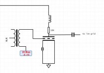
The 26 will be DC using Rod Coleman's current regulators. I therefore can't include a 10R sense resistor in the cathode (I am building in measuring posts and a switch for meter measurements without disturbing the amp). Seems logical to me to place it directly on the anode pin as in the attached.
With only 6mA expected through the valve, it's actually going to be very difficult to measure that. Should I simply measure across the anode choke ? Lundahl 1667 with 2k4 DCR so that 14.4V drop is going to give a much more accurate measurement. Think I answered my own question.
Any comments ?
Just a quick check - I'm redrawing the circuit diagram to better understand the circuit loops and also pin down the grounding schema.
The 26 will be DC using Rod Coleman's current regulators. I therefore can't include a 10R sense resistor in the cathode (I am building in measuring posts and a switch for meter measurements without disturbing the amp). Seems logical to me to place it directly on the anode pin as in the attached.
With only 6mA expected through the valve, it's actually going to be very difficult to measure that. Should I simply measure across the anode choke ? Lundahl 1667 with 2k4 DCR so that 14.4V drop is going to give a much more accurate measurement. Think I answered my own question.
Any comments ?
Attachments
Last edited:
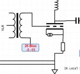
Try to use two -for example- 22R 1W resistor from each filament pin, connect together as "virtual cathode", and use 1 or 10R 0.5-1W from "virtual cathode" to GND.
Checked Rod's instructions. Connecting the reg like the attached avoids the current going through the sense resistor, so problem solved.
I still might be better using the anode choke for the 26 though, with such a low current.
Attachments
71A bias looks fine. The grid resistor of about 430-500KΩ, for preference.
Thanks Rod
I'm trying to get my head around the circuit flow for the RC coupling from 26 to 71A.
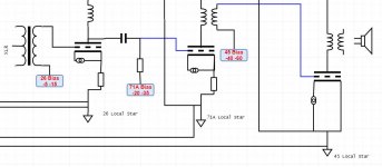
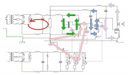
First diagram shows the full circuit - upper half is the positive rail and the flows through the 3 valves. lower half is the negative rail used for the 3 trimmers providing fixed bias to the valves. This also shows the grounding schema.
Second diagram is where I'm starting to draw out the circuit flows, partly to improve and solidify my understanding of it and also to make it easier to see where loops may not be optimal.
XLR to 26 is via transformer, as is 71A to 45. 26 to 45 is RC coupled. If the 71A were cathode biased then the grid resistor would be grounded and it would be a nice tight loop. Because its fixed bias the grid resistor "grounds" at the trimmer output giving the bias. So the signal loop is
26 anode -> Coupling Cap -> 71A Grid Resistor -> Trimmer Stack -> Bias ground -> Star Ground -> 26 ground -> 26 cathode
Do I have that right ? Is there a way to optimise that loop ?
Attachments
The Capacitor that bypasses the bias voltage should be located near to the triode that it biases, and connect to the local ground.
The bias network resistors/poti should probably be locally mounted too. There's no problem running the supply to different places - use screened cable is you are worried about pickup.
The bias network resistors/poti should probably be locally mounted too. There's no problem running the supply to different places - use screened cable is you are worried about pickup.
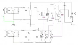
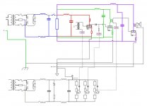
Actually just drawing out the diagram in that way has really helped me already. Improved version attached...
BLUE = primary PSU
RED = 26 PSU loop
GREEN = 71A PSU loop
PURPLE = 45 PSU loop
That's cleared up where the PSU returns need to go, separate to the grounds.
Just that fixed bias loop worrying me now.
BLUE = primary PSU
RED = 26 PSU loop
GREEN = 71A PSU loop
PURPLE = 45 PSU loop
That's cleared up where the PSU returns need to go, separate to the grounds.
Just that fixed bias loop worrying me now.
Attachments
The Capacitor that bypasses the bias voltage should be located near to the triode that it biases, and connect to the local ground.
The bias network resistors/poti should probably be locally mounted too. There's no problem running the supply to different places - use screened cable is you are worried about pickup.
Thanks Rod - will mull that over
The Capacitor that bypasses the bias voltage should be located near to the triode that it biases, and connect to the local ground.
The bias network resistors/poti should probably be locally mounted too. There's no problem running the supply to different places - use screened cable is you are worried about pickup.
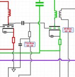
Something like this Rod ?
The pots and caps will be located right next to the triodes - I'm just getting my head around the loops so I keep the current flows separate.
Attachments
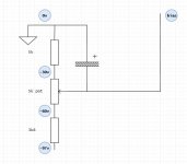
Calculation of capacitor to bypass the Fixed Bias trimmer
How does one calculate the value of the capacitor needed at this point ?
So in the attached example, the bias sees the 5k resistor + a variable resistance from the pot (up to 5k), so between 5k and 10k. Is it simply
1 / (2 * pi * R * F)
where R is 5k to 10k
and F is desired frequency corner (-3db)
eg 1 / (2 * pi * 10k* 5) = 3uF ?
Attachments
How does one calculate the value of the capacitor needed at this point ?
You'd want to look at the amount of ripple that you see at the pot wiper. You can also put a cap from the 3.6K resistor/pot junction to ground to provide some additional filtering. Here's a decent (short) page to read through about these types of filters:
Low Pass Filter - Passive RC Filter Tutorial
If you've done any work with loudspeaker crossovers, this will look very familiar.
Now, when it comes down to putting a cap from wiper output to ground, this is certainly something you can do, but if you make it too big, you'll have sluggish bias adjustments since the cap has to discharge when you turn the bias pot. I think you could get away with as much as 470uF here, but I don't see much of a reason to go beyond 47uF.
Those tutorials are excellent and I've seen that one before - thanks for the link though. My question is really whether the resistance in this case should be the parallel paths for the AC fluctuations - the path to ground (via 5k and 50% of the trimmer) and the path to B- (via 3k6 and 50% of the trimmer).
- Status
- This old topic is closed. If you want to reopen this topic, contact a moderator using the "Report Post" button.
- Home
- Amplifiers
- Tubes / Valves
- All DHT Circuit Advice