... trying to avoid any silicon in this amp, at least for now, patly for purity and ... I'll fit a 50mA fuse in the cathode leg while I get it working. I can then bypass it later to hear what difference it makes to the sound.
Then strictly use the thermal fuses. The-made-of-glass ones will for sure screw the sound. The metal/ceramic envelope tubes also is the must! ))
Then strictly use the thermal fuses. The-made-of-glass ones will for sure screw the sound. The metal/ceramic envelope tubes also is the must! ))
I have to ask how a <25mm length of wire in a glass cylinder can possible "screw" with the sound. I hand wire my amps point to point and there could be 15 meters of wire inside. Never have I considered the sonic effect of an AGC fuse.
I don't fuse the cathode or anode circuits as I use a combination of grid and cathode bias. (27V (3x9V) grid batteries and a CCS (70ma) in the cathode. If the CCS shorts it won't destroy the tube and the heatsink can be smaller.
I'm building a power amp using 45 valves for output, interstage transformer coupled and with grid bias (trimmer surrounded by resistors to make the trimmable range what I need). The grid bias will be fed from a separate rectifier tube and LCLC filtered.
If the grid bias fails there's obviously a risk to the output tube. I'm looking into using a relay so that if the grid bias supply fails the output tube B+ will be cut.
Usually, the concern in fixed bias is the adjustment pot since the wiper arrangement is a weak point. The bias power supply if designed properly can be considered just as reliable as any p.s. The issue then comes down to keeping sufficient negative voltage on the power tube grid to prevent tube runaway if the adjustment pot were to become open. The easy solution is to simply put an appropriately sized resistor from the pot input to the wiper output. If the wiper loses contact and becomes open the resistor will supply a high negative voltage on the grid putting the power tube in cutoff. The only issue would be the adjustment range of the pot will be less with the safety resistor.
> energise at 12mA ? The specs I've looked at on RS or Mouser seem to specify coil voltage
AND resistance. Do math.
Don't assume "24V relay"; you want a ~~12mA relay at <120V. And the "12mA" is soft, you can pick a different "10K" to get a different current.
The BIG problem is---
> output tube B+ will be cut
This needs a 250V contact. My dim memory suggests that dozen-mA relays may not come that large on the contact side. *Especially* as a DC rating, because DC can arc forever. (AC is easier to break because it stops 100 times a second.)
This would be interesting except I can not find it in stock:
RM85-2011-35-1110 ---- 110V DC 25,200 Ohms - (77V-280V)
http://www.mouser.com/ds/2/16/RM84-RM85-RM87-612793.pdf
The RM85 series has a DC13 rating of 0.1A at 250V. This may cover a couple'45s. It might not do that all day and all night such as busy elevator service; DIY audio is less demanding and has a technician on-call at all times. <G>
4.3mA, no resistor, direct connect. It _will_ hold to 77V, and maybe MUCH lower, which could be bad. An empirically determined series resistor will make it frop-out much sooner. However relays are sometimes much "stickier" than their specs imply. (As long as it DOES drop-out when you break the wire, it's good for the intended purposes.)
Mouser does have small stock of RM85-2011-35-1012, 12V 360 Ohms so 33mA and over 3 Watts in a drop resistor.
AH! Mouser does stock RSB1A120FD which is 110V coil 25K. The contact DC rating is just 28VDC at 12 Amps, but 300V DC is allowed at some unspecified lower current?
Considering the very wide and poorly specified drop-out voltage/current of most relays, I do think you want some more precise trigger.
Way back in the day we could buy "sensitive" relays which took low current and dropped-out pretty predictably, because they just-barely pulled-in at rated power. But those days are gone. I went looking for an old clunker (ratchet relay) and paid quite a lot for a vintage not-quite part.
______________________
> drags the output valve screen supply low
OK, but Type '45 does not know what a screen supply is?
Usually, the concern in fixed bias is the adjustment pot since the wiper arrangement is a weak point. The bias power supply if designed properly can be considered just as reliable as any p.s. The issue then comes down to keeping sufficient negative voltage on the power tube grid to prevent tube runaway if the adjustment pot were to become open. The easy solution is to simply put an appropriately sized resistor from the pot input to the wiper output. If the wiper loses contact and becomes open the resistor will supply a high negative voltage on the grid putting the power tube in cutoff. The only issue would be the adjustment range of the pot will be less with the safety resistor.
Thanks for that suggestion. I have designed the values of resistors above and below the trimmer pot to give me the trimmable range I'm looking for and to keep everything within one quarter of it's rated dissipation, but of course you're right if the trimmer fails open the tube can runaway. A large resistor in parallel won't affect the range much at all, say 100K in parallel with the 1K trimmer. I'll do the checks but excellent suggestion thanks.
Thank you PRR. I was struggling to work out the math because I didn't understand the basics of relays. I friend talked me through it (with the coil DCR in series with the resistor forming the voltage dividor).
Thank you also for taking the trouble to explain some of the problems with using them and pointing out a couple of options I might look at. I very much appreciate the guidance.
Thank you also for taking the trouble to explain some of the problems with using them and pointing out a couple of options I might look at. I very much appreciate the guidance.
>
The BIG problem is---
> output tube B+ will be cut
This needs a 250V contact. My dim memory suggests that dozen-mA relays may not come that large on the contact side. *Especially* as a DC rating, because DC can arc forever. (AC is easier to break because it stops 100 times a second.)
OK I'm going to ask what may be a REALLY dumb question - but that's how we learn right ?
")
The plan would be for the relay to engage or cut the ground return of the 45 power rail. No grid supply, no B+ supply. The voltage being switched (in the ground circuit) can't be 250V ? If the circuit is engaged then most of the voltage is being dropped across the 45 valve ?
If I'm thinking of that incorrectly please illuminate.
If I'm thinking of that incorrectly please illuminate.
I think you are
Think of a 250v battery and a 250 ohm resistor across it where 1 amp flows. It doesn't matter where in the circuit the switch to break the current flow is placed, the open (or opening) switch still sees 250 volts.
Breaking the current flow to the anode of a valve leaves the supply at its B+ voltage and the anode at zero volts. Relay sees B+ voltage across the contacts.
Breaking the current flow in the cathode earthy end sees the cathode rise to B+ voltage and the ground point remain at zero. Relay again sees B+ across the contacts.
If that happens because the B+ is interrupted right on the load couldn't we move the relay earlier in the psu chain like an auto standby switch? Does it matter that the output valves will have to discharge the capacitors for a second?I think you are
Think of a 250v battery and a 250 ohm resistor across it where 1 amp flows. It doesn't matter where in the circuit the switch to break the current flow is placed, the open (or opening) switch still sees 250 volts.
Breaking the current flow to the anode of a valve leaves the supply at its B+ voltage and the anode at zero volts. Relay sees B+ voltage across the contacts.
Breaking the current flow in the cathode earthy end sees the cathode rise to B+ voltage and the ground point remain at zero. Relay again sees B+ across the contacts.
I'm sure there are other ways to do it. You might run into the problem of needing auxiliary power rails to run the protection circuitry though.
Just thinking aloud as to a possible method...
Use a high voltage FET as the control element with it arranged to be 'permanently' biased on. Use the relay contacts in reverse (so normal operation = contacts open) to remove bias when the monitored supply fails.
Something like that could be very simple.
Does it matter that the output valves will have to discharge the capacitors for a second?
That depends. One of my amps is blessed with a few milifarads...there are certainly others like that
The relay contact in post #24 will have DC through it - I suggest your relay contact won't last long at all in that scenario - even contact bounce when powering on will be ugly due to initial surge currents.
You should really check your bias supply first for its voltage regulation with such a load as a relay coil. A variac would allow you to identify pull-in and let go voltage levels.
You could use part of the KT88 example circuit, where a psuedo cathode bias resistor is inserted if there is no/low bias. The contact then has a much easier time in life, even if there is a fault current, as the OT winding resistance is a limiter, and the cathode bias resistor is a voltage snubber. If you weren't so ss averse, then an optomos device with NO 'contact' status is a modern part that is so simple to implement for this application.
One concern with very low rated current fuses is that their resistance can be significant, depending on how close to the rated current occurs for normal operation in say an output stage cathode. But imho fusing perhaps the power supply CT may be a reasonable compromise, depending on how many tubes are in parallel, and the configuration of output stage. And with what looks like costly PT, OT and valves, then imho you really should be protecting each valve diode anode with additional series 1N4007's (multiple for the 475VAC windings).
From a reliability perspective, the bais adjust wiper should be protected too.
Last edited:
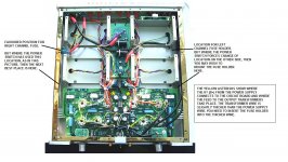
If this is for the Yaqin 100b then there should be two fuses on the rear panel for protection of the B+ lines. Some 100b's do not have fuse holders fitted and the rear panel, without special milling, will not allow fuse holders to be fitted. The next best option is to fit them on the sides as shown in the detail attached. Choice of fuses comes next and I looked for the most fast fuses, labelled Ultra Fast. These are expensive at 17.41 GBP for a pack of 10 but still cheaper than a new output transformer. I tried 200mA at first but these suffered from nuisance blowing so I increased the rating to 315mA. These seem to be the best and have saved the output trannys on a 100b owned by a friend of mine. The type of fuse is made by Mersen Part No. Z084018P and can be found under UK RS distributor as stock number Z084018P | Cartridge Fuse, FF, 315mA | Mersen
It should be possible to find the same fuses in the United States.
Must stop drinking wine on Sunday afternoons! Just realised you have a 300b and not a 100b but the concept may be of some use though the fuse rating may be lower.
Good Luck.Les
It should be possible to find the same fuses in the United States.
Must stop drinking wine on Sunday afternoons! Just realised you have a 300b and not a 100b but the concept may be of some use though the fuse rating may be lower.
Good Luck.Les
Attachments
Last edited:
I my latest push pull amp I did, I added fuses for each power tubes on the cathode side, but before the sensing bias current 1R resistor.
Here the voltage is low so no need for expensive HV fuse.
Worked great but you have to play around the fuse value.
I started with 125mA fast blo and I am now at 250mA after multiple tries and blowing fuses.
The current swing is much more than I anticipated at high volume.
So you may use that design to protect your big expensive tube in your amp.
> what may be a REALLY dumb question
I don't know if there are "dumb" questions. (Nobody born knowing this stuff.) But this sure is a popular question. (Usually formulated as an assertion, FWIW.)
> cut the ground return .... The voltage being switched (in the ground circuit) can't be 250V ?
The switch (relay contacts) do NOT know where "ground" is.
As Mooly says: yes, zero when contacts closed, but when they open they fly to the full 250V. Through a "resistance" (the tube), so it can't be an infinite current arc, but a 50mA 250V arc is 12 Watts in a teeny contact.
Worse: the real circuit contains an inductor (transformer). Using dirt-scratch logic, assume the speaker is connected, the voltage will kick-up *double* for as long as the inductor holds flux. Basically a half-cycle of your lowest audio frequency. So many milli-Seconds before it settles back to 250V.
Agree that relay contact bounce adds much wear.
I am pondering a very large cathode resistor, shorted-out when bias is good. {EDIT- ah, Tim said this.} Pencil 1K (10W), maybe 2K? When that is in (and bias is zero) the '45 falls to a lower-power self-bias condition which is safe. (Need to plot this.) When the -60V bias happens, relay shorts this resistor, we in fixed-bias. Need to think about worst-case sequences. Still considerable voltage across the contacts when they open. Still some OT kick-up, mildly muted by the tube and its grid held low.
I think you are working-out why we NEVER used such "protection" schemes back in the day, on anything less than a kilo-Watt transmitter stage.
Last edited:
Yes nowadays one could generalise and say that OPT and expensive valve protection is of more interest especially for vintage unobtanium models, and protection parts are easier to obtain and better. But the tricky part is to apply the protection with care, as the amp likely needs to be protected from the newly added protective part !
A cathode fuse really needs a protective bypass so as to limit cathode voltage rise (to protect the valve if that wasn't the cause of the fault).
Same applies for a controllable fuse (ie. a relay contact - whether that is a physical relay contact, or an electronic optomos switch) in the same location. But in this scenario, the bypass also helps protect the contact/switch.
The bypass can be a simple 150V 5W zener (suits all normal output stage valves for the heater-cathode voltage rating). The bypass could also be a pseudo cathode bias resistance (as per GEC KT88 design example), or a higher value lower wattage resistor (sized to also constrain cathode voltage).
If a controllable switch is used, then it may only be activated by a certain condition (ie. loss of bias voltage), and may need protection itself from other sorts of faults (eg. over-current from another failure mechanism).
I'm liking the idea of an optomos in series with a fuse, with a total bypass 150V zener, but haven't tried that. It does seem an onerous level of protection, but I guess if you have a bunch of NOS matched GEC KT88's in circuit, and each one costs over $100 then ....
Last edited:
As stated in a previous post by another member. I did the same and used a cheap PIC to monitor both cathode current and the presence of a -ve bias voltage. This controlled the Power and HT feeds.
VTA ST-120 - Born in the UK...
VTA ST-120 - Born in the UK...
As stated in a previous post by another member. I did the same and used a cheap PIC to monitor both cathode current and the presence of a -ve bias voltage. This controlled the Power and HT feeds.
VTA ST-120 - Born in the UK...
Do you have a link to any technical details on the protection provided?
Hi Mate,
Sorry, all in my head as it was done on the fly.
Basically the following
1 ) Allows for a toggle on/off function
2 ) Allows for remote on/off
3 ) Monitors the voltage across the individual cathode resistors.
4 ) Controls the mains power to the transformer
5 ) Provides a delayed HT switch on feature.
6 ) Drives each LED individually to indicate the correct standing current in each output valve. (fast flash too high, slow flash too low, on ok)
7 ) Monitors the -ve bias rail and will not enable HT unless this is present.
8 ) If excessive current is detected in any one of the output valves will shut off the amplifier.
9 ) Special bias setting mode where the high/low tolerance of the LED indications is tightened to allow for precise setting to ~500mv as per spec
In terms of other features the main power transformer and HT relay are PIC controlled. When powering off, the mains relay is de-energised 0.5 seconds before the HT relay to prevent arcing at relay contacts. The mains relay has a contact suppressor to reduce arcing.
The inputs to the PIC are protected against HV should a flash over occur in any output valve which would maybe open circuit the 10R cathode resistor.
The -ve bias voltage is monitored by an NPN transistor. The base bias is set such that the -ve bias voltage (fed by a resistor) is just enough under normal conditions to keep the transistor from conducting. Should the bias voltage go astray the transistor then conducts and signals to the circuit to turn off the power to the amp.
Haven't had a melt down or a flash over yet so fingers crossed. It's just there, as stated, to provide a degree of protection and confidence should I leave the room.
Steve
- Status
- This old topic is closed. If you want to reopen this topic, contact a moderator using the "Report Post" button.
- Home
- Amplifiers
- Tubes / Valves
- All DHT Circuit Advice