
This is a
DC 12V 24V to DC 200-450V 70W High Voltage Boost Converter Step Up Power Supply.
I am using one of these to feed an ECC83 and two EL84's 250 volts.
Output irons are Lundahl.
Toroid custom wound for heaters. Big one.
Power supply for eh... power supply is a big one from a car stereo demo rack. 13.7 volt regulated, good for about 20 amps.
The sound is super duper and it is absolutely dead quiet between songs.
Have ordered one more for dual setup.
Have anyone tried something like this?
Is it ******* at the Alamo? Swearing in church?
Cannot find much online.
Weird. Its awesome!
You may have better luck in the Instrument forum, there are quite a few guitar amps using SMPS for HV.
Solid State High Voltage Regulated Power Supply For Vacuum Tube Circuits - YouTube
Solid State High Voltage Regulated Power Supply For Vacuum Tube Circuits - YouTube
") .
.Just a quick title search turned up the following, there are many more if you look harder...
http://www.diyaudio.com/forums/tubes-valves/277460-smps-tube-kit.html?highlight=smps
http://www.diyaudio.com/forums/tubes-valves/70566-smps-home-audio.html?highlight=smps
SMPS for B+ discussion
http://www.diyaudio.com/forums/tubes-valves/277460-smps-tube-kit.html?highlight=smps
http://www.diyaudio.com/forums/tubes-valves/70566-smps-home-audio.html?highlight=smps
SMPS for B+ discussion
I have tried this. But it seems easier to destroy then an alternative :
DC10-32V to DC +-45-390V 780V! dual output adjustable converter capacity charger | eBay
DC10-32V to DC +-45-390V 780V! dual output adjustable converter capacity charger | eBay
I got two of these in the mailbox yesterday, haven´t tested them yet:
DC-DC 10-32V to 45-390V High Voltage Boost Converter Step-up Booster Module TB | eBay
My plan is to use them together with a 24V 6A SMPS to provide B+ and heater voltage for an PL36 SE amp.
DC-DC 10-32V to 45-390V High Voltage Boost Converter Step-up Booster Module TB | eBay
My plan is to use them together with a 24V 6A SMPS to provide B+ and heater voltage for an PL36 SE amp.
I have bought the same SMPS module pictured in the first post but I haven't tried it yet, because it scares me. It screams cheap from all the sides. The seller specification sheet says: 70W DC-DC non-insulated SMPS; input 12V 7A (3A min at startup) / 24V 3A with undervoltage protection at 7.6V; output 200-450V; switching frequency 160 KHz.
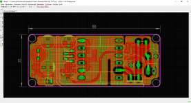
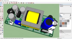
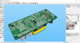
There is neither a manufacturer marking or a regulatory mark. It does not have enough termal grease on the power mosfets, and the flyback diode is tacked to the heatsync with a blob of glue. The PWM controller is a mistery 8 pin DIL chip with chinese markings. Input and outputs filtering is minimal with no inductors. There is space for a current sensing resistor, but on my board a jumper is fitted in its place. There is no protection against reverse polarity at the input. The output protection device is a 5x20 fuse on the negative (!) rail. On my board, it's rated 10A. The transformer is probably the only interesting bit of this design, but it looks smaller than a proper 70w part. I would rather size it a 40-50W. This would still be 160mA at 300V, plenty of current for many tube amplifiers. The two mosfets are rated 80A at 70V (HY1707). There is no insulation between the PCB and the bottom metal heatsync; clearance is only 4mm.
I will surely try it, but only after adding better protection, EMI filtering, a better heatsync with proper component mounting, and probably also a metal shield. This would give it a better chance to survive more than a few weeks of real use, and will restore radio reception on the surrounding area.
Edit: I forgot to add that on my board there is a error: the output terminal is marked input. This has been confirmed by the support forum of the seller. Just follow the PCB traces of the 450V capacitor and you will see the real output terminal. Well, at 10$ is a fun experiment at least.
I also have a APPj PA0901A amplifier (2x EL84 + ECC83) that is factory fitted with a SMSP power supply. The output filter configuration is CL CL CL C (a string of 4 capacitors and 3 inductors), and yet a residual squeaking noise from the SMPS is udible from the speakers. The PWM chip on my APPj amplifier is a TOP250YN - it does have a relatively low switching frequency. I would have used a quasi-resonant chip instead, still cheap but less EMI issues.
Last edited:
Well I was also a bit reserved to try this until I saw the youyube video posted here earlier. That tipped me over.
Been playing loud for hours and the damn thing is barley luke warm!
4 mm clearance should be enough? Gonna pull it out of the puny box and add real heatsinks and so on.
Mighty impressed!
BUT: it needs a good dc power supply! With a 90 watt laptop supply (might have been faulty) it did not work.
Sound and led was slowly pulsing. Lack of power I guess.
The heatsink may be enough if the current draw is low, but the termal paste should be applied correctly. A foil of insulating material will take care of the smallish clearance at the bottom.
The power supply should be able to surge at least 3A at startup. This will trip the overcurrent protection of some laptop power supplies - use a bigger one or a beefy but cheap 12V DC regulated LED power supply. The input power supply terminals should not be referenced to ground. There is a electrical path between the positive input terminal and the negative output terminal.
The power supply should be able to surge at least 3A at startup. This will trip the overcurrent protection of some laptop power supplies - use a bigger one or a beefy but cheap 12V DC regulated LED power supply. The input power supply terminals should not be referenced to ground. There is a electrical path between the positive input terminal and the negative output terminal.
I had one of these analysed;
DC10-32V to DC +-45-390V 780V! dual output adjustable converter capacity charger | eBay
it is a ZVS converter, Zero Voltage Switching;
means switching frequency is not constant, but varies with load;
moreover, regulation is done such that there are bursts of fast switching followed by gaps (pause) with no switching at all;
it is neither a flyback nor a classic boost converter;
the switching as such is not audible but the repetition frequency of the gaps falls in the audio range - depending on load - and may vary randomly ...
couldn't use it as B+ supply so it found it's place as PS for a tube tester.
don't know about the OP's version whether it's different ...
Based on Pete Millett´s 10W flyback converter I´ve designed a 24W version.
Pete has simulated successfully the 24W version and recommended to swap to another more powerfull WE 30W transformer.
Very busy, the modification is still pending.
Intended to be used for tube preamplifier and amplifier.
P.S. all this ebay chinese converters are load of crap.
JP
Pete has simulated successfully the 24W version and recommended to swap to another more powerfull WE 30W transformer.
Very busy, the modification is still pending.
Intended to be used for tube preamplifier and amplifier.
P.S. all this ebay chinese converters are load of crap.
JP
Attachments
- Home
- Amplifiers
- Power Supplies
- High Voltage Boost Converter - sacrilege?