Hi
Newbie to this forum and looking forward to participating. Also hoping this is the place to get some advice about the feasibility of constructing a vintage amp?
Just for fun I'd like to have a go at building a 1954 Mullard design for a 5 valve 10 watt high quality amp (I believe affectionately known as the Mullard 5-10).
I have a copy of Mullard's construction booklet and there is also a quite detailed article on the amp on The National Valve Museum website (Mullard 5-10. Ten Watt Amplifier)
I have chosen this particular amp because I happen to have the booklet, but I have read on wikipedia (Mullard 5-10 - Wikipedia) that the circuit design was famous for its unique sound reproduction, so it will be interesting to find out.
The valves are no problem (EF86, ECC83, EL84 and GZ30), but I am concerned about the two transformers (mains and output). I doubt I will be able to get hold of original NOS ones so can someone help by advising me of a suitable modern alternative for each?
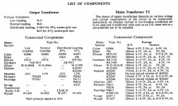
I have attached the relevant section of the booklet which refers to the transformers, the choice of which I understand depends upon loading. Three arrangements of the output stage are possible: normal loading, low loading and distributed loading. For want of any specific knowledge I guess it would be sensible to opt for normal loading.
Hope someone can help.
Newbie to this forum and looking forward to participating. Also hoping this is the place to get some advice about the feasibility of constructing a vintage amp?
Just for fun I'd like to have a go at building a 1954 Mullard design for a 5 valve 10 watt high quality amp (I believe affectionately known as the Mullard 5-10).
I have a copy of Mullard's construction booklet and there is also a quite detailed article on the amp on The National Valve Museum website (Mullard 5-10. Ten Watt Amplifier)
I have chosen this particular amp because I happen to have the booklet, but I have read on wikipedia (Mullard 5-10 - Wikipedia) that the circuit design was famous for its unique sound reproduction, so it will be interesting to find out.
The valves are no problem (EF86, ECC83, EL84 and GZ30), but I am concerned about the two transformers (mains and output). I doubt I will be able to get hold of original NOS ones so can someone help by advising me of a suitable modern alternative for each?
I have attached the relevant section of the booklet which refers to the transformers, the choice of which I understand depends upon loading. Three arrangements of the output stage are possible: normal loading, low loading and distributed loading. For want of any specific knowledge I guess it would be sensible to opt for normal loading.
Hope someone can help.
Attachments
Spiatrie, Edcor makes a lot of power transformers which will work for this project as well as Hammond and others. You can choose one with adequate filament current on a single 6.3v winding to handle all the tubes including the rectifier since the EZ81 is a indirect heated cathode type of rectifier. If I was building this and wanted to keep a tube rectifier, I would likely change the rectifier tube to a 5v variety since most power transformers you will find will have a 5v winding separate for the rectifier tube.
As for output transformers, Transcendar makes a nice 8k unit with ultralinear taps as does Edcor, Hammond and many other more expensive brands. I have built an EL84 push pull linear amplifier with the Transcendar transformers and I can highly recommend them.
Mickeystan
As for output transformers, Transcendar makes a nice 8k unit with ultralinear taps as does Edcor, Hammond and many other more expensive brands. I have built an EL84 push pull linear amplifier with the Transcendar transformers and I can highly recommend them.
Mickeystan
I use Majestic Transformers in Poole Dorset. They manufacture to the original design or can adjust to your requirements. Electrical Transfomers & Electrical Transformer Manufacturer UK
I would use the original EZ81 rectifier, don't know where you got GZ30 from. GZ30 is a 5Z4 at 125mA but EZ81 is rated at 150mA.
I would use the original EZ81 rectifier, don't know where you got GZ30 from. GZ30 is a 5Z4 at 125mA but EZ81 is rated at 150mA.
from the 5-10 schematic link:
The basic sensitivity of the circuit with this amount of feedback is 40 mV for the rated output power, and the sensitivity when the tone controls are included is 600 mV.
I'm assuming you won't be using the tone controls - either way, this will be one sensitive amplifier requiring a lot of padding from the volume control and/or preamplifier.
A possible mod to drop the gain: convert the EF86 pentode circuit to triode.
Thank you for the replies. I will have a look at the transformers on offer from the companies you have recommended. Can you also have a look at the specs for two transformers I have found from VVT and tell me if you think these would work (see below)?
I have studied my booklet more thoroughly and have discovered I should go with a low loading output stage because I intend to use the amp with music and voice only. For low loading the booklet recommends the use of a EZ80 rectifier.
(JonSnell: This comprehensive 86 page booklet I have contains a lot more information and certain differences to other printed versions of this amp and that's where I got the GZ30 from. The booklet specifies the use of a GZ30 for normal and distributed loading).
When opting for low loading the booklet specifies a mains transformer with the following secondaries: 300-0-300; 3.15-0-3.15;0-6.3 (for the EZ80). I was wondering if this one from VVT would meet the bill:
VTH15774
VTH15774-1300 - HT Transformer for RH84SE Amplifier
And I was wondering if this one from VVT would be suitable for the OP transformer...
VTP12925
VTP12925-1300 - Mullard 5-10 PP UL Output Transformer EL84 10 Watt 6600 ohms/valve
(kstagger: I am intending to include the tone control circuit as recommended by Mullard in the booklet. Given that I have found differences in my booklet to other shorter versions on the web I will scan the schematic I am working on and will post a copy here. It is OK to do so because it is out of copyright)
Mullard 5-10 build experience
What a co-incidence - I built one of these last year as an exercise to get into valve amp construction myself! I've found these forums invaluable and I’ve learned a lot in the process so I offer the following design considerations:
As you say you are unlikely to be able to source NOS parts so things like the transformers will almost certainly be different dimensions from the original and therefore the chassis design will need to change somewhat. Therefore, do you intend to stick with the overall Mullard design or take the opportunity to re-design the chassis and layout to your own design? In his book ‘Building Valve Amplifiers’ Morgan Jones uses the Mullard 5-10 circuit to do a chassis design exercise. It’s quite different to the original Mullard design but very attractive and practical. I chose to adopt this approach and it has worked out very well. A suitable chassis is available from Bluebell Audio.
I’d go for distributed loading as this was touted to give the best results overall (power vs distortion) with the design. If I remember correctly Mullard recommended 20% taps on the output transformer (as opposed to 43% used by other designs of the era). I got my transformers from Sowter and although expensive are very high quality. They have a custom wind service which costs no more in general than their off-the-shelf products. They already have a design for 20% taps so you could use that. Or you could specify a design with both 43% and 20% taps and experiment! And then just not use the taps if you want to try normal or low-loading. They also supply different configurations of output impedance – 4x4ohm windings for example, or 1x16 ohms etc. so you can have a lot of flexibility with different loads. The transformer you would need is based on the 1431s. They also supply a suitable mains transformer – the MO35s – although this has an extra heater supply and higher H.T. current capability than needed as it can supply an external valve pre-amp as well. Again they can custom-wind something for you if they don’t have it on the shelf. I would go with the EZ81 rectifier as it can handle all loading types.
As already mentioned the design means the amp is very sensitive and the main problem I found was that it is noisy. This is very noticeable in quiet passages of music and will be a problem particularly for you as you are intending to use it for voice. The noise is mainly hum/buzz and comes from both heater AC supply (50Hz) and H.T. rectifier (100Hz). This manifests itself as a problem in the first stage (the EF86) and is therefore amplified all the way through the amp. However, there are a few things you can do:
1. It will definitely reduce noise generally if you wire the EF86 for triode operation as this will reduce the high gain of the stage - but that might not help much if you are using the tone controls. I can post the circuit here if you like although I think it can be found elsewhere in these forums. You could also make it switchable between triode and pentode operation.
2. I strongly recommend you use a DC supply for the EF86 heater which will get rid of most of the 50Hz hum component – a simple and effective design can be found at Simple DC Heater Supply for EF86 etc.
3. I also added an extra level of filtering to the H.T. (150ohms in series with 33uF to ground) before the main reservoir capacitor which helped reduce rectifier (100Hz) hum/buzz, without reducing the H.T. voltage appreciably.
Having made these mods to my amp I can barely notice any hum now with my ear pressed close to the speaker and the volume at max (no signal) so I think that’s all that can reasonably be done with this design.
I hope this helps. Good luck with your amp!
Another coincidence - I just built a Mullard 5-10 stereo! I used VVT transformers (mains and output) the ones they recommended for a Mullard 5-10 stereo set-up. I used distributed load/ultralinear. It uses a GZ34 instead of 2 x EZ81s, but aside from that adaptation I’ve followed as faithfully as possible the circuits in the 1993 reprint of Mullard’s 1959 “Tube Circuits for Audio Amplifiers”. From first firing up, it sounds wonderful – a rich chocolaty sound, very low hum and hiss. However, I was concerned about the measured DC conditions which varied quite a lot from the published table. Anode voltages especially in the input stages (ECC83, EF86) were much higher. I sweated for weeks trying to figure this out. Then I found an old thread on Vintage Radio with a link to the PDF for 1954 circuit. Circuit was the same BUT the DC conditions were quite different. In fact they were very similar to my measurements – so great relief there. But it begs the question: what happened within Mullard in those 5 years from 1954 to 1959 to change the DC conditions for the same circuit? The AVO used has same specs. And why does my amp conform to the earlier version and not the later? Any ideas anyone? I attach pics of the two tables …. Aside from that I’m enjoying a sound I’d almost forgotten from 50 years I would like to explore now alanpharwoods suggestion of trimming the EF86.
Attachments
Thanks DF96 that sounds the most plausible explanation. minor correction to my last post - I meant to say "I would like to explore now alanpharwoods suggestion of 'trioding' the EF86." but auto spell changed it to 'trimming'.
On Spiatrie's concerns on transformers - it may be the mains tranny he is thinking of using/or already using is a bit light. VVT suggest this one for the 5-10 stereo (this is the drop through version) VTH13332-1340 - Mullard 5-10 stereo HT Transformer Have you stated building Spiatre? If either you or alanpharwood have time to upload some pics, It would be great to see your babies!
On Spiatrie's concerns on transformers - it may be the mains tranny he is thinking of using/or already using is a bit light. VVT suggest this one for the 5-10 stereo (this is the drop through version) VTH13332-1340 - Mullard 5-10 stereo HT Transformer Have you stated building Spiatre? If either you or alanpharwood have time to upload some pics, It would be great to see your babies!
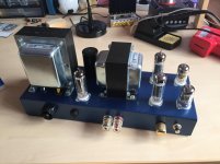
jeromepiercy I'm using Electro Harmonix valves throughout and wondering if that is why I had a noise problem (with the EF86) and had to go to some lengths to fix it. You don't mention any noise problems so what valves you are using? As DF96 says it's probably the manufacturing variation - I'm using recently manufactured vs a Mullard product of the '50s but I have to say the DC voltages I measure are very close to spec. So long as they are relatively near it's no problem being as the valves are cathode-biased. Here's a pic of my finished amp. I'm getting 13W RMS into 16 ohms.
Attachments
Transformers
Hi spiatrie, I've just been taking a look at your transformer question and I have the following observations:
Output transformer: looks ideal, has all the features I mentioned in an earlier post, so you can experiment with different loading configurations.
Mains transformer: a concern here. While the HT looks OK (80mA for normal loading is worst case) the LT side has problems (if I'm reading the spec correctly). The 5V 3.5A winding is superfluous since all the valves in the design use 6.3v heaters. This leaves you with two windings. Typically one winding is dedicated to the rectifier - if you use the EZ80 that's the 0.6A winding used leaving the 1.6A winding to supply the other four valves. The EL84s take 750 mA each, the EF86 needs 200mA and the ECC83 300mA so you don't have enough current! And you are restricted to low loading even though you have the other loading options with the output transformer. You need a minimum of 2A on the secondary to be safe. And 1A on the other to use the EZ81.
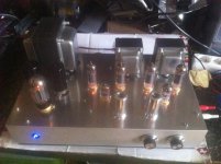
alanpharwood I'm using valves all supplied by karltone.co.uk - 2 x matching pairs of EL84s, 2 x ECC83s, 2 x EF806s and one GZ34 instead of EZ81, as I built it stereo. A crackle noise and distortion problem did develop with one channel until the valves were warmed up. Swopping the EL84s cleared the crackle but moved the distortion to the other channel - so I suspect one of the EL84s is a bit faulty. However the distortion goes away after a few minutes. I may order another pair of EL84s. I'm planning to build the stereo pre amp and take the LT and HT from the main amp. I'm inclined to take up alanpharwoods suggestion of supplying the heaters for the EF86 in the main amp and the pre amp heaters with DC, as I suspect the hum will only increase otherwise. The gain on the main amp is huge - it's a no tone controls version - I'll save them for the pre-amp. Still sounds b***** marvelous hooked up to a bluetooth input!
Attachments
Transformer
I think that mains transformer could have worked with the original statement where he said he was proposing using a GZ30 - which has a 5V heater and draws 2A. Then the other two windings would just be able to supply the 6.3 v requirement between them. But I was reacting to the later statement that talked about the EZ80.
I think that mains transformer could have worked with the original statement where he said he was proposing using a GZ30 - which has a 5V heater and draws 2A. Then the other two windings would just be able to supply the 6.3 v requirement between them. But I was reacting to the later statement that talked about the EZ80.
Call me Al
jeromepiercy I noticed in your post no. 13 you mentioned interest in building the Mullard stereo preamp - I've thought about this too but I have concerns about noise especially given my recent experience with the EF86 - the preamp uses two per channel. The info in the Mullard spec gives hum and noise as 58db below 20W ("microgroove")which is very poor by today's standards. Coupled with the high sensitivity of the 5-10 it now does not seem a good match (to me). Would be a good topic to debate but maybe we should start a new thread - what does our friendly Moderator think?
jeromepiercy I noticed in your post no. 13 you mentioned interest in building the Mullard stereo preamp - I've thought about this too but I have concerns about noise especially given my recent experience with the EF86 - the preamp uses two per channel. The info in the Mullard spec gives hum and noise as 58db below 20W ("microgroove")which is very poor by today's standards. Coupled with the high sensitivity of the 5-10 it now does not seem a good match (to me). Would be a good topic to debate but maybe we should start a new thread - what does our friendly Moderator think?
I have studied my booklet more thoroughly and have discovered I should go with a low loading output stage because I intend to use the amp with music and voice only. For low loading the booklet recommends the use of a EZ80 rectifier.
From the Mullard datasheet linked below, pages C10 through C15 show distortion figures for the different loading conditions. For the low and high load conditions (6K & 8K pentode connection), THD is between 1 and 2% for most of the operating range. For the UL connections, THD is on average below 1% and in the case of the 8K and 43% tapping, it's below 0.5% with the D5 component not even shown (below instrument's capability). Since you're building new and have a choice for an OPT, I would take this info into consideration.
http://www.mif.pg.gda.pl/homepages/frank/sheets/129/e/EL84.pdf
Pre-amp for Mullard 5-10
I'm up for it Al. I had a gut feeling that the 2 EF86's were going to be way too sensitive for the already sensitive 5-10. Guts are ok but science is better. I'm going to take a deeper look at the data and alternatives. Good screening and DC heaters would be a start. Then there's probably some good wheels out there already invented. This could be an interesting journey. My aim with a pre-amp is to use a magnetic pick-up for a turntable + some variety of other useful inputs + some tone controls. Suggest name for new thread - 'New build: Pre-amp for Mullard 5-10'. Rules say we can post new threads, but haven't figured out how to yet. I'm new to this game. Call me Jez ...Would be a good topic to debate but maybe we should start a new thread - what does our friendly Moderator think?
Hi I have been doing Audio Amplifiers since 1955 when I built my first M-5-10 amplifier for a cousin of my dad’s. In those days I obviously used the EZ81, but now with all the solid state rectifiers available I now use 1N4007 diodes with a 220 Ohm 10W resistor in series with the connected diode cathodes. I have a very critical friend who plays guitar in a band and he said that he could not tell the difference between my 220 Ohm loaded solid state rectifiers and the real EZ81 rectifier. I trust him as a critical listener. I do remember that powerline hum was a problem using AC heating of the EF86, but by twisting the heater wires an keeping the heater wiring away from the input grid the hum could be made to inaudible. For instance unlike Radio receivers, you had to center-tap the heater wiring and not run the heater unbalanced with respect to chassis ground.
Hans J Weedon. (Now 80).
Hans J Weedon. (Now 80).
- Status
- This old topic is closed. If you want to reopen this topic, contact a moderator using the "Report Post" button.
- Home
- Amplifiers
- Tubes / Valves
- New build: Mullard 5-10