Having built 5-10's about 60 years ago whilst a teenager and subsequently built a pair of Williamsons, may I say there is no comparison in the sound quality. One way of improving the sound from the 5-10's would be to reconfigure the first EF86 as a triode. The 6BQ5's probably have to stay as they are.
Switching interference from 1N4007
Hi
I absolutely agree that there is a world of difference between the 1N4007 and the UF4007 recertifies, But it is normal practice to put a 0.01uF 630V capacitor for noise suppression across each rectifier-diode anyway, so i did not mention it, which I should have. My apologies.
Hi
I absolutely agree that there is a world of difference between the 1N4007 and the UF4007 recertifies, But it is normal practice to put a 0.01uF 630V capacitor for noise suppression across each rectifier-diode anyway, so i did not mention it, which I should have. My apologies.
More on Mullard 5-10 Amplifier.
Hi again (today)
I took a look at the schematic for the Mullard 5-10 amplifier. If the input sensitivity is too high for today's signal sources, and you therefore get too much hum, I believe that using the EF86 in triode mode is a good way to go. That should lower the gain of the circuit by a factor of 4. We convert the tube connection to a triode by connecting grid2 and grid3 to the anode (plate if you will). Although grid 2 connected to anode is all that is really needed, also connecting grid3 to anode will reduce the electron "confusion" in the grid2 to anode space. I believe the tube used in the triode mode that way is a tiny bit more true triode like.
Electrically, there is no reason not to use an ECC83/12AX7 in that space, but the hum control is somewhat better in the EF86 than the generic 12AX7. there are special ECC83 verities with better filament hum control, but they tend to run into more money. Remember, though: When you use the EF86 in the triode mode you no longer need R5 and C2 and should not connect them. Also when you use the triode-connected EF86 you should change the feedback resistor by a factor of 4, because as a triode the EF86 has a quarter of the gain, pentode connected. For the 8 Ohm case you should use 5.6k with a 620pF capacitor in parallel.
Good luck.
Hans J Weedon
All real ECC83 have low hum; not all modern valves marked as ECC83 actually are ECC83, some are 12AX7.
With any mod to the 5-10 or 5-20 first stage you need to check that the LTP phase splitter is still balanced, as the ECC83 circuit is quite sensitive to the anode voltage of the first stage.
With any mod to the 5-10 or 5-20 first stage you need to check that the LTP phase splitter is still balanced, as the ECC83 circuit is quite sensitive to the anode voltage of the first stage.
Hi
I absolutely agree that there is a world of difference between the 1N4007 and the UF4007
recertifies, But it is normal practice to put a 0.01uF 630V capacitor for noise suppression across each rectifier-diode anyway, so i did not mention it, which I should have. My apologies.
Snub UF4007s too. Less noise, from the outset, allows for near silence.
All real ECC83 have low hum; not all modern valves marked as ECC83 actually are ECC83, some are 12AX7.
I'm sincerely interested, and do not know the answer to this question:
What are the exact differences between 12AX7 (or 12AX7A) and ECC83?
From everything I've read, 12AX7 (and 12AX7A) is the US identifier for the high mu twin-triode known in Europe as the ECC83. Not true?
--
The 12AX7 was developed in the US. In Europe Philips/Mullard developed an improved version called ECC83, which was very similar apart from having a low hum heater and possibly some other minor internal changes (possibly lower noise cathode surface?). Then in the US a copy of the ECC83 was produced called 7025 - the numerical 'name' indicates 'special quality' in the US. Later, some US valves labelled 12AX7 also had the low hum heater.
Modern manufacturers take no notice of these details, so a modern 'ECC83' may actually be a genuine ECC83 with low hum heater or a 12AX7 with traditional heater.
I don't know what is meant by 12AX7A.
Modern manufacturers take no notice of these details, so a modern 'ECC83' may actually be a genuine ECC83 with low hum heater or a 12AX7 with traditional heater.
I don't know what is meant by 12AX7A.
Hi.
I just looked up what the difference between the 12AX7 and the 12AX7-A. According to the (US) GE documentation the 12AX7-A is a lower microphonics and lower filament hum pickup version of the 12AX7. I trust the GE documentation because they became almost the sole manufacturer of vacuum tubes after WWII.
Hans J Weedon.
On the balance of the ECC83 in the Mullard 5-10 circuit. One of the elegant features of the Mullard circuit is how the ECC83 grids are connected.
By connecting the anode of the EF86 directly to on grid of the dual triode with just a 1 meg Resistor to the other grid, bypassed, the circuit is self balancing.
By doing that they avoid a complete low frequency pole inside the feedback circuit. That makes the amplifier easier to stabilize at the low frequency end of the spectrum.
What should be checked however is the voltage distribution of LTP phase splitter. The DC voltage from cathode to anode of the phase LTP phase splitter triodes should be 1.2 to 1.4 times the voltage across the 100k load resistors. That puts the LTP in the “sweetspot” as far as drive and linearity (distortion) of the phase splitter. Also the original description of the circuit recommends that the two 100k load resistors of the LTP be slightly different. The first resistor should be about 3% lower in resistance than in the second stage. That tends to AC balance the grid drives to the output tubes. This is a little overkill but gives a little bit lower second harmonic distortion overall.
Hans J Weedon.
A modern EL84 perhaps?
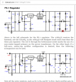
If you don’t need tone controls and the gain of the standard Mullard is too high consider building a modern EL84 PP amp. Get hold of copy of Morgan Jones book, Valve Amplifiers. Starting on page 298 Jones gives the circuit (see attached) for an EL84 PP amp that uses reclaimed vintage “iron” but can be built with new transformers too. The voltage gain and phase splitter is an ECC88. The only thing that might put you off is the voltage reg for the ECC88. See the picture below (link included too) of a Broskie regulator that is not to onerous to build. PS-1 Solid-State Regulator Kit
For use in the M. J. amp I’d use a 47uF cap for C8. To set the reg to 285 volts change R6 to 26.7K. Of course, all parts to the right of C6 can be eliminated when using it in the M. J.
Regards, Steve
Attachments
For the most part, the "A" suffix on U.S. 7 & 9 pin mini types indicates controlled heater warmup time. That feature was of importance in low cost TV sets that employed series heater strings.
The Sovtek 12AX7LPS is a genuine 7025 equivalent and constructed with a spiral wound, hum bucking, heater. LPS = long plate spiral.
The Sovtek 12AX7LPS is a genuine 7025 equivalent and constructed with a spiral wound, hum bucking, heater. LPS = long plate spiral.
Hi.
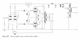
I never really liked the Concertina phase splitter as a driver for an output stage, especially when used in an amplifier with relatively low output power. The reason for this is has nothing to do with normal operation, but during overload conditions. During overload, especially in an amplifier with overall negative feedback, the cathode of the phase inverter will “see” a low impedance when the output tube goes positive into grid conduction. At that time the triode is forced into a high gain mode with respect to the anode load. A sharp negative pulse on the the triode plate will drive the opposite grid much too far negative.
That is all fine, but now the average voltage stored on the output tube coupling capacitors will get a wrong voltage. Especially the cathode driven capacitor will get the wrong bias voltage, the grid of the power tube will act like a rectifying diode. That wrong DC voltage will upset the bias balance in the output tubes, resulting in a net DC current in the output transformer, tending to saturate the iron. The overall negative feedback will try to correct all theese nonlinearities and the amplifier will start to sound “funny and strange”.
In other words the Cocertina phase-inverter in an amplifier makes it sound strange as a result of overloads. At least that has been my observation. One of my designs started to oscillate at over 100MHz for a brief moment after overload. The use of a UHF dual triode as the ECC88 will probably make this effect even more difficult to find and correct. At least i was puzzled.
Hans J Weedon
Last edited:
Not quite. The feed arrangements for the second grid introduce an LF pole in much the same way as a coupling cap would. The first stage anode, the LTP grids, and the ground are connected in series via a coupling cap and a resistor - it is just that in the Mullard circuit the cap is moved to the other side of the LTP differential input. It still does essentially the same job.HJWeedon said:By doing that they avoid a complete low frequency pole inside the feedback circuit. That makes the amplifier easier to stabilize at the low frequency end of the spectrum.
Hi.
I never really liked the Concertina phase splitter ....The reason for this is has nothing to do with normal operation, but during overload conditions. In other words the Cocertina phase-inverter in an amplifier makes it sound strange as a result of overloads.
So the amp lets you know when you are clipping. Kind of like a red line on the tach... seems like a bonus.
Yes I agree that the amplifier sort of tells you that it is overloading, but that is not how I want to be told, the reason is that a vacuum tube amplifier has a very specific way of overloading that only makes the sound seem loud, not distorted. Case in point: My son has a 35W tube amplifier that he says sound louder than an 80W solid State amplifier. The solid State amplifier limits hard at the peaks, whereas the tube amplifier just rounds off the peaks when IT overloads. When his kids have partiets he wants them to use the tube amplifier not to burn out speakers, which the Solid State amplifier is known to do.
Hans J Weedon.
Hans J Weedon.
Last edited:
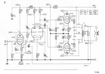
Long time ago, as I remember correctly in 1984, Elektor published a 5-10 amplifier in the above mentioned EF86 strapped to triode version, readily available with PCB's in those days. Perhaps someone may find this article.
Best regards!
Correct, November 1984 Issue 115.
Alan
Attachments
With any mod to the 5-10 or 5-20 first stage you need to check that the LTP phase splitter is still balanced, as the ECC83 circuit is quite sensitive to the anode voltage of the first stage.
I don't think that a varying EF86's plate voltage will disbalance the LTP, as it's both grids are connected via the 1M/100n RC low pass. The first tube's plate voltage has a strong impact on the tail current, though.
Best regards!
- Status
- This old topic is closed. If you want to reopen this topic, contact a moderator using the "Report Post" button.
- Home
- Amplifiers
- Tubes / Valves
- New build: Mullard 5-10