I've been reading the many (many, many, many) posts about local negative feedback around an output stage. I picked up somewhere that local feedback performed by taking signal from the plate of an output tube can go equally well to either that output tube's grid (plate-grid local feedback, aka "Schade") or to the cathode of the driver tube (RCA Tube Manual style). Are these basically the same thing, done differently?
I was also reading about the various ways of putting NFB into a circuit. Series-derived, series-applied, parallel-derived, parallel-applied, in all combinations. I'm sure I'm just being dense, but I'm not following the meanings of those definitions, although I get that applying NFB reduces gain in all cases (as opposed to positive feedback, which boosts gain once applied).
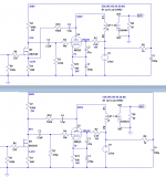
Anyhow, here are two circuits I modeled in spice, to illustrate the question. R10 and C4 feed back the audio signal from the plate of U2. To keep things simple, I AC-coupled the feedback loop from the output tube's plate, so that the high voltage there wouldn't influence DC conditions elsewhere in the circuit. The top schematic is plate-cathode, the bottom one is plate-grid.
--
So, the question is, of these two ways of applying NFB around the output stage of a simple SE pentode amp, is one better than the other? Is one better than the other in certain situations, but not in others? Are there downsides to using one or the other when driving the complex load presented by the OPT with a speaker connected to its secondary?
--
PS - Yes, DC-coupling the feedback to the drain of the input DN2540 is possible, by taking R10 directly from the 6BQ5 plate and going to the DN2540 drain, with no DC-blocking C4 (and removing the decoupling network R9/C5). I wanted to keep this comparison apples to apples, with identical DC conditions for both examples.
I was also reading about the various ways of putting NFB into a circuit. Series-derived, series-applied, parallel-derived, parallel-applied, in all combinations. I'm sure I'm just being dense, but I'm not following the meanings of those definitions, although I get that applying NFB reduces gain in all cases (as opposed to positive feedback, which boosts gain once applied).
Anyhow, here are two circuits I modeled in spice, to illustrate the question. R10 and C4 feed back the audio signal from the plate of U2. To keep things simple, I AC-coupled the feedback loop from the output tube's plate, so that the high voltage there wouldn't influence DC conditions elsewhere in the circuit. The top schematic is plate-cathode, the bottom one is plate-grid.
--
So, the question is, of these two ways of applying NFB around the output stage of a simple SE pentode amp, is one better than the other? Is one better than the other in certain situations, but not in others? Are there downsides to using one or the other when driving the complex load presented by the OPT with a speaker connected to its secondary?
--
PS - Yes, DC-coupling the feedback to the drain of the input DN2540 is possible, by taking R10 directly from the 6BQ5 plate and going to the DN2540 drain, with no DC-blocking C4 (and removing the decoupling network R9/C5). I wanted to keep this comparison apples to apples, with identical DC conditions for both examples.
Attachments
Last edited:
local feedback performed by taking signal from the plate of an output tube can go equally well
to either that output tube's grid (plate-grid local feedback, aka "Schade") or to the cathode
of the driver tube (RCA Tube Manual style). Are these basically the same thing, done differently?
Not the same, since Schade is feedback around a single stage.
http://www.electronics-tutorials.ws/systems/sys29.gif
Using the driver cathode is feedback around two stages.
More distortion, more phase shift, error signal derived through a device junction.
https://upload.wikimedia.org/wikipe...px-Operational_amplifier_noninverting.svg.png
Last edited:
One thing I'm seeing in spice sims is that if you use a triode as the driver stage, plate-grid (parallel?) NFB doesn't work well. Replacing the triode with a depletion mode MOSFET (orders of magnitude higher gm) makes the plate-grid feedback work very well. The MOSFET is also super-easy to implement. Using a pentode as the driver works pretty well for plate-grid NFB, but never as well (or as easily) as the depletion mode MOSFET.
However, if you must use a triode as the driver, then plate-cathode (2-stage, series) NFB works very well, at least in the sims.
Does that make any sense?
However, if you must use a triode as the driver, then plate-cathode (2-stage, series) NFB works very well, at least in the sims.
Does that make any sense?
You want to use something that is a very linear voltage to current converter working into a vertical load line. If you look at triode characteristics, you can see that a triode wants a horizontal load line, but a vertical one will give awful results as far as linearity goes. Pentode is much more linear into a vertical load. Cathode degeneration will further improve that linearity but will reduce gain.
Great stuff, thank you everyone.
OK, I'm finding it very easy to get a good looking simulation going with a DN2540 driving an EL84, with plate-grid (parallel) feedback. That's the schematic in the bottom half of the attachment (post 1). The thing is, I'm finding it very difficult to get similarly good looking results with a pentode as the input stage. I figured 6AU6A would work, but it seems to need high voltages at plate and screen. With a B+ of only 270V, there's not much for it to work with. If I use 6J9P (E180F, 6688) then I get reasonable results, but the gain is very, very high (much higher than with the DN2540 in the first stage).
How do I set up the pentode so that it's working into a vertical load line? Do I want to use a relatively small value plate resistor and adjust plate+screen current by adjusting values of the screen grid dropping resistor and cathode resistor?
I've read that plate-grid NFB works from the plate into the combined load of the output pentode's grid leak resistor in parallel with the rp of the driver pentode. If I reduce the value of the input stage pentode's plate resistor (say to 10k), how will that influence the feedback voltage divider? Will it load it down?
--
Is "Schade" feedback any kind of NFB around a single stage, whether series or parallel applied?
Here's the original 1938 paper by Schade at RCA, see figure 33.
http://www.clarisonus.com/Archives/TubeTheory/Schade 1938 Beam Power Tubes.pdf
It's shunt (also called parallel) feedback that is applied around a power output tube.
Last edited:
It's not that you -want- a vertical load line for the shunt (Schade) plate to grid feedback, it's just that it is mostly unavoidable in the shunt case. The feedback resistor, with the large opposite phase plate signal on it, makes for a low impedance node where it connects with the driver plate. (which has opposing phase, they fight each other, trying to hold V variation to zero)
Optimum case: Often designers will put a Mosfet follower after the driver plate, with a series source resistor to the output tube grid plus the feedback resistor (and cap) from the output plate. That way the driver tube can have a desirable high Z load, and the series source resistor and output feedback resistor make for a very constant divider ratio for the feedback effect.
The triode driver case has variable plate resistance causing the N Fdbk divider ratio to change with current as well as badly loading the triode with low Z. But putting the Mosfet follower and series source resistor after the triode driver plate can fix those problems.
The pentode driver is not a free ride either, since it has a 3/2 (or more likely 2.0) power law V to I conversion from its grid. So some cathode degeneration is needed to linearize that.
The Mosfet driver with high gm is even easier to linearize with some source degeneration. But a common source mode driver will have input capacitance issues. While the follower modes are relatively safe.
Tubes naturally like high impedances for linearity. So the shunt (Schade) feedback is somewhat of a misfit unless using the Mosfet follower fix.
Schade series feedback (using an interstage xfmr) is the natural high Z scheme. However, good interstage xfmrs are expensive and cause phase problems for any global N feedback.
Two tube N Fdbk:
Putting the plate drived N feedback back to the driver cathode (or crossed over in P-P to the driver grids) puts the gain of two tubes in the loop. This will drastically reduce distortion, but can be tricky for stability with more gain in the loop. Putting the N Fdbk to the driver cathode increases the input Z and input Voltage swing needed. Usually not a problem for tubes to handle.
Putting the plate derived N Fdbk back to the driver grids (crossed over P-P) gives two tube loop gain also. But lowers the input Z of the driver grid, which can be a problem for the front end tube to drive linearly and adequately (V swing).
Then there is an infrequently seen version where the plate derived N Feedback resistors go back to driver screen grids (cross over, P-P). This is not going to be as linear, but produces a triode gain function from the (pentode) drivers (grid1 to grid2 triode gain function preserved). If you like triode P-P sound, then this can be your baby.
..
Last edited:
It's shunt (also called parallel) feedback that is applied around a power output tube.
Sorry, that is incorrect. Schade applied series feedback through a clever interstage transformer setup that allowed him to change feedback ratios by changing out resistors. It is not a setup that lends itself well to building amplifiers but it was useful in demonstrating the benefits of local feedback in the output stage for his white paper.
Look carefully at the schematic of his setup and you will see that a portion of the output voltage signal is applied in series with the input voltage. I too assumed that it was parallel applied feedback at first, since everyone here was calling parallel applied feedback "Schade" feedback.
Last edited:
Rongon,
Another resource that might be helpful might be just reading up on op-amp circuits. The standard inverting amplifier is parallel applied feedback. The non-inverting amplifier is series feedback. Think of the grid of a tube as the inverting input and the cathode as the non-inverting input.
Another resource that might be helpful might be just reading up on op-amp circuits. The standard inverting amplifier is parallel applied feedback. The non-inverting amplifier is series feedback. Think of the grid of a tube as the inverting input and the cathode as the non-inverting input.
I too assumed that it was parallel applied feedback at first, since everyone here
was calling parallel applied feedback "Schade" feedback.
Yes, in the original paper, but since very few use interstage transformers now,
it's mostly applied as shunt feedback.
Yes, in the original paper, but since very few use interstage transformers now,
it's mostly applied as shunt feedback.
The most elegant way of implementing "Schade" feedback is a simple cathode feedback winding, which is the series feedback case. It's just not very flexible if you want to change the ratio.
The most elegant way of implementing "Schade" feedback is a simple cathode
feedback winding, which is the series feedback case.
Right, like Audio Research, Mac, Luxman. I used similar circuitry in some custom amps
that I built and sold in the 70s. Needs a healthy driver stage though.
http://www.4tubes.com/SCHEMATICS/BY-BRAND/Audio-research/D70MKII_schematic_signal.jpg
Last edited:
Great stuff, thank you everyone.
OK, I'm finding it very easy to get a good looking simulation going with a DN2540 driving an EL84, with plate-grid (parallel) feedback. That's the schematic in the bottom half of the attachment (post 1). The thing is, I'm finding it very difficult to get similarly good looking results with a pentode as the input stage. I figured 6AU6A would work, but it seems to need high voltages at plate and screen. With a B+ of only 270V, there's not much for it to work with. If I use 6J9P (E180F, 6688) then I get reasonable results, but the gain is very, very high (much higher than with the DN2540 in the first stage).
The main problem is that the DN2540 has gm to burn, a magnitude of order greater than a 6AU6. It can work, but it's gonna take a bit more effort to come up with a good design.
From the spec sheet:
The 6AU6A is a miniature sharp cutoff pentode primarily designed for use as a high gain radio or intermediate frequency amplifier. Its low grid-plate capacitance and high transconductance make it especially suited to high frequency, wideband applications
It was never intended as an audio amp, and the included plate characteristic was shown with that in mind. As a result, it needs some high voltages and low plate loads.
How do I set up the pentode so that it's working into a vertical load line? Do I want to use a relatively small value plate resistor and adjust plate+screen current by adjusting values of the screen grid dropping resistor and cathode resistor?
For audio amplification, you don't want that. You get the best linearity with light plate loads, since deltaV= R X deltaI, the larger R is, the smaller deltaI is for any given deltaV.
I've read that plate-grid NFB works from the plate into the combined load of the output pentode's grid leak resistor in parallel with the rp of the driver pentode. If I reduce the value of the input stage pentode's plate resistor (say to 10k), how will that influence the feedback voltage divider? Will it load it down?
--
The problem here is you get yourself into an "ouroboros" situation. Reducing the plate resistor means reducing Rf, but that increases the loading, thus demanding a smaller Rf that increases the loading: wash, rinse, repeat. The problem is that the effective value of Rf is reduced below its DC value by a factor of (1 + Av) the same Miller Effect that makes the effective input capacitance look larger than its static value. That's usually why the driver is a pent, as you can get better linearity from a pent than a heavily loaded small signal triode.
You'll probably have to limit the amount of lNFB you apply, and use gNFB to clean up whatever messes remain.
Below is an interesting twist on the usual (often called Schade or shunt Schade) local shunt N Fdbk scheme. This was posted by Goldenbeer last year.
It uses -crossed- shunt feedbacks (a P-P design) to apply POSITIVE feedbacks to the driver loads via bootstrapping. (the P feedback resistors become the driver load resistors) This can be used to slant the driver (triodes) load lines in the opposite sense from usual. (neg. impedance loads) Which can be used to produce opposite 3rd harmonic distortion versus the final (class A necessarily) output stage (for 3rd harmonic cancelling).
This avoids the low Z loading problem of a conventional shunt "Schaded" triode driver as well, and provides additional loop gain for a global N feedback loop. (or for another encompassing local N Fdbk loop) (see post #45 in link)
I haven't seen any further developments to this concept in the form of an actual amplifier. Check the end of that thread for a possible caveat due to global N Fdbk maybe losing control at frequency extremes and some fixes.
Would be interesting to hear from Goldenbeer about any further developments on this interesting driver scheme.
http://www.diyaudio.com/forums/tubes-valves/289449-advice-budget-valve-amplifier-3.html#post4672554
Note:
This is definitely tricky multi-loop feedback design in motion here. Not recommended for the timid or beginner designers. Hard to ignore however, doing a lot of stuff better. The P Fdbks alone will increase the output impedance, so some encompassing N Fdbk(s) required to lower Zout, and prevent possible oscillation.
https://frank.pocnet.net/sheets/093/6/6SN7GTB.pdf
..
Attachments
Last edited:
I noticed Gary Pimm's Tabor amp uses a 6AU6 LTP DC-coupled to 1624 outputs. Isn't the 1624 very similar to an 807, and therefore to a 6L6GB? (Not 6L6GC, but that would be compatible.) If so, then that's another example of a simple local shunt feedback PP pentode design.
An externally hosted image should be here but it was not working when we last tested it.
- Status
- This old topic is closed. If you want to reopen this topic, contact a moderator using the "Report Post" button.
- Home
- Amplifiers
- Tubes / Valves
- Plate-Grid vs. Plate-Cathode local NFB - Is it the same?