These suggestions are speculative, and the effects will be unknown until the final project if done. How can you say that arbitrarily slapping in a current source or making some other tweak will improve the design? Its all very well to compare interelectrode capacitance values, but useless without a way to compare circuit A with circuit B.
Obvious design goals on this device are:
1) provide the correct load to the cartridge
2) provide some gain
3) isolate the eq components from the circuit source and load
Speculation is great, but component values have to be tweaked empirically after everything is in place, using a reverse eq input and frequency response graphs. And, I would think occasional tweaking might be needed now and then to compensate for tube aging.
Speculation on my part, of course.
RA
Dear RA
There no speculation with regard to MM capacitive loading.
Load the Magnets!!! - [English]
Hagerman Technology LLC: Cartridge Loading
Discussion on MC Cartridge Loading
Admittedly, some MM cartridges are a bit better and handling different capacitive loads than others.
Regarding gain - You must have gain for RIAA correction, then you must have gain AGAIN just to get the signal somewhere close to line level. If the first gain stage has a high output inpedance (ie. 12ax7), then this will affect the RIAA correction as it ages.
So, what to do? Find a high gain stage that has a lower output impedance (ie. low Ri triode, or triode strapped pentode). This saves you from occasional tweeking.
However you are not saved from the effect of capactive load on your MM cartridge. Finding suitable solutions are not so cheap or easy. Real work is often involved here...
btw - I love MM cartridges. I find them just as good as MC cartridges when very welll implemented (which is extremely seldom).
Ian
Yes, 50pF is really good ")
In the mean time I have made a BOM for this project and during the component selection I have also increased the size of the 47 uF capacitors !
I have also added a jumper to use both 9A and 9AJ pin configuration to accommodate heater supply for ECC82 or 6N1P (which seem to have good audio specs ?).
I hope everything is OK since I am ready to send the PCB to the manufacturer...
Marc
Attachments
Nobody found it but there was a big error on the PCB : the pin-out of the ECC82 / 12AU7 was reversed, I mean view from bottom instead of top
Hopefully I discovered that just after I had sent the files to the manufacturer and I could change it immediately
Now I have just to wait and hope there is no other error ?
For your information I have added the final version below... For a better readable PCB, I didn't enable the ground planes.
Cheers,
Marc
Attachments
You did not take my advise of an on-board 7805 regulator, nor did you adopt merlins
serial conncted filaments, both will reduce the current. 12V ( or 16.5 if pc97 is connected
in series with ecc82, no resistor needed as done by merlin). An on-board 7812 AND serial
filaments would be the optimal, all fed from an 18VAC transformer/rectifier/first ca combination outside the board.
Even if dc filament is done outside the board any small amounts of hum might creep
into the signal at these low voltages.
I have seen your advise but I am planning to use a separate Power Supply board to accommodate the regulation for both heater and high voltage supply and since I want also to power a linear buffer stage I prefer to keep all heater lines at 6.3 V DC. Anyway power dissipation in each resistor will be less than 1 W !
Also I didn't want to make a bigger board and in case I have to use a three terminal regulator I would prefer a LM317, it is much less noisier than the 78xx series.
Thanks for your support,
Marc
Also I didn't want to make a bigger board and in case I have to use a three terminal regulator I would prefer a LM317, it is much less noisier than the 78xx series.
Thanks for your support,
Marc
Marc,
One more thing to check - the ZVN054A has a dissipation rating of 700mW. Its voltage and peak current rating is fine.
You might want to check if you are safely within that rating with R14, R33 at 27K. If it is dissi[ating more than say 350mW you may want to choose a higer power rated MOSFET. There are some newer devices rated at 1.5 watts with similar low Crss. On another thread Eli (Duttman)saidf he uses IRFB20 when the ZVN0545 doesn't have enough power capability, you could check it out.
Cheers,
Ian
Last edited:
Hi Ian,
Thanks for the warning !
I try to look to other depletion mode MOSFET in TO92 package (PCB is in manufacturing...) and I have found two interesting alternatives :
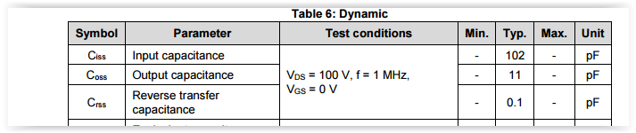
SSN1N45B from Fairchild, Vds = 450 V, Id = 500 mA, P = 2.5 W, Rds =3,4 ohm, Crss = 6.5 pF
STQ3N45K3 from ST (with Zener) Vds =450 V, Id = 600 mA, P = 3 W, Rds = 3.3 ohm, Crss = 3 pF
To compare the ZVN0545A has also Vds = 450 V, but Id is 90 mA, P is only 0.7 W and Rds is 50 ohm, Crss is 4 pF....
The device from ST is a little more powerful, has a lower Crss and include a Gate-Source Zener protection. As a bonus its price is only 0.58€ each in qty of 10 on Mouser The ZVN0545A is 1.18€ and the SSN1N45B is the cheapest at 0.48€ !
What do you think about using the ST part and avoiding the external Zener ?
The other suggestion from Peter did not fit in this project because it's a TO220 package, far too big
Cheers,
Marc
Thanks for the warning !
I try to look to other depletion mode MOSFET in TO92 package (PCB is in manufacturing...) and I have found two interesting alternatives :
SSN1N45B from Fairchild, Vds = 450 V, Id = 500 mA, P = 2.5 W, Rds =3,4 ohm, Crss = 6.5 pF
STQ3N45K3 from ST (with Zener) Vds =450 V, Id = 600 mA, P = 3 W, Rds = 3.3 ohm, Crss = 3 pF
To compare the ZVN0545A has also Vds = 450 V, but Id is 90 mA, P is only 0.7 W and Rds is 50 ohm, Crss is 4 pF....
The device from ST is a little more powerful, has a lower Crss and include a Gate-Source Zener protection. As a bonus its price is only 0.58€ each in qty of 10 on Mouser
The ZVN0545A is 1.18€ and the SSN1N45B is the cheapest at 0.48€ !What do you think about using the ST part and avoiding the external Zener ?
The other suggestion from Peter did not fit in this project because it's a TO220 package, far too big
Cheers,
Marc
...try this STF7N60M2
Am I reading the STF7N60M2 datasheet correctly? Does that really say its Crss is 0.68pF? Is that possible? If so... Wow! What's the catch?
Or am I confusing Crss with Cinput?
--
Last edited:
Higher power rating is good, make sure pin out is the same, it is a pain to bend leads around to suit the PCB. BUT don't go higher power rating than absolutely necessary, higher power rating MOSFETS generally have higher lead capacitances.
Because it is in Source follower mode then Ciss is not critical but for optimum HiFi performance Crss is important. if you check out the various data sheets you will see that Crss modulates with Vds (that is with the audio signal in source follower mode, coz the Vdrain is fixed but the Vource follows the audio signal) and that is the problem. From the datasheets you will also see that as long as you maintain a Vds of at least 30V, even on peak positive going signals, then Crss is low and reasonably constant.
Cheers,
Ian
Last edited:
No, the pin out is not the same, the gate on pin 1 instead of the middle one but it is easier to adapt it than a TO220
Thanks for the explanation, I learn a lot with you ! Crss is only 3 pF with the STQ3N45K3 from ST, this is even better than the ZVN0545A which is also becoming more difficult to find... I have bought to test it.
Cheers,
Marc
but it is easier to adapt it than a TO220 Thanks for the explanation, I learn a lot with you ! Crss is only 3 pF with the STQ3N45K3 from ST, this is even better than the ZVN0545A which is also becoming more difficult to find... I have bought to test it.
Cheers,
Marc
Am I reading the STF7N60M2 datasheet correctly? Does that really say its Crss is 0.68pF? Is that possible? If so... Wow! What's the catch?
Or am I confusing Crss with Cinput?
--
i use it on ecc83 (very high ri, no prob) gyrator, sound is sharp as razor
Drives endstage very wellWent thru all mfg., only ST has so low Cgd fets..
oh, another.. http://www.st.com/content/st_com/en...esh-gt-700-v/mdmesh-k5-series/stf3ln80k5.html
Attachments
Last edited:
Cmiller = 4pF + (70+1)*1.1pF = around 85pF
So you need to get the phono cables under 100pF.
Hi Ian,
well, it depends on the cartridge, doesn't it? You're quite right for AT cartridges, but, e.g., Shure types in general accept larger load capacitances, such as 500pF. Even the then state-of-the-art ELAC 796HSp or AKG P8ES Super Nova, respectively, accept values of up to 300pF.
Btw, standard RG174 coax cable has a capacitance of just 50pF/m.
Hi Marc,
the PC93 and PC900 virtually appear very similar. So, why no try the latter one? Both are high gm, high µ triodes with remote characteristics (which doesn't do excessive harm in low signal applications like a RIAA input stage). Unfortunately, no publication of plate curves available for both of them, so an exact comparison is unpossible :-(. And yes, within the AF range it doesn't harm if one (of several) cathode pin is left unconnected.
Yes, the PC97 (not 93 !) and the PC900 are similar but unfortunately they aren't pin compatible ! That is the reason of the two jumpers to select pin 1 or 2 for the grid. I think that the PC900 has been introduced later and may be it's an improved version ?
I will test both... And by the way I have just received the PCB's today
Marc
I will test both... And by the way I have just received the PCB's today
Marc
Attachments
Btw, standard RG174 coax cable has a capacitance of just 50pF/m.
I found a spec page on RG174 coax, here:
RG174 Cable | View RG-174 coax specs from Allied Wire & Cable
The capacitance is atated to be 30.8pF/foot, or 101.24pF/meter.
The inner conductor is copper clad steel.
--
The Project is moving ahead, board is partially built, I need to order some components that I haven't in stock...
By the way I changed some resistors value in the RIAA network to use more common value (E12 series). I replaced :
200k + 7.5k = 207.5k with 180k + 27k = 207k
and
30k +1.8k =31.8k with 27k + 4.7k = 31.7k
The change is lower than the 1% tolerance of the resistors and should not modify RIAA correction
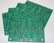
Some photos of the work in progress...
Cheers,
Marc
By the way I changed some resistors value in the RIAA network to use more common value (E12 series). I replaced :
200k + 7.5k = 207.5k with 180k + 27k = 207k
and
30k +1.8k =31.8k with 27k + 4.7k = 31.7k
The change is lower than the 1% tolerance of the resistors and should not modify RIAA correction
Some photos of the work in progress...
Cheers,
Marc
Attachments
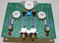
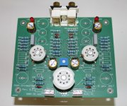
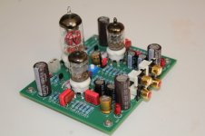
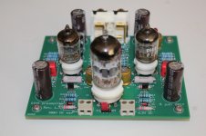
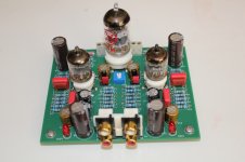
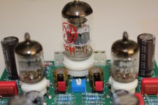
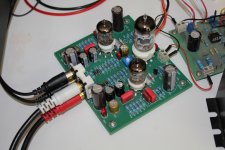
After a short trip I am back and i have finished the RIAA amplifier (see the photo) but I have some trouble with one channel
On the fourth photo you see the red jumpers for the PC900 option, on the fiftieth photo the second MOSFET is not yet soldered, with only the first working channel completed, at that time I was still happy
After I completed the first channel with the STQ3N45K3-AP, it worked immediately. I found it a little noisy but as I made the test with a old turntable and a old Stanton head in an open environment (no shielding) I didn't investigated that further in a first time... I checked the temperature of the MOSFET and found it a little bit warm but not hot
Therefor I decided to use the ZVN0545A on the second channel to avoid to turn the leads of the transistor, as Ian pointed out they are not fully compatible !
That was a big mistake ! Not only the second channel didn't work, but the MOSFET became immediately very hot. I stopped everything and de-soldered it (what a mess with plated through holes) to replace it with a STQ3N45K3, however I had the same symptom : MOSFET very hot and no sound
It is exactly the same layout than the other channel, I don't understand... I cannot make voltage measurement because I am worrying that the transistor will die if I don't remove the power immediately ! Any suggestion ?
Cheers,
Marc
Attachments
- Home
- Amplifiers
- Tubes / Valves
- Merlin RIAA Preamp