Here is an idea for those who don't like the fact that normal error correction or negative feedback always ends up correcting the error after the fact. Thus creating higher harmonics, as the error in the error signal propagates endlessly around the loop. The basic idea here is to generate a slightly time advanced error feedback signal for "just in time" addition to the input. Admittedly, one can just use a small capacitor in the feedback to phase advance the feedback signal, but this does not take into account the dynamic distortion curve of the amplifier to prevent generation of higher harmonics. So, here is the plan:
To the input signal of the amplifier, a small, high frequency, sawtooth or triangle wave dither signal is added before application to the amplifier. Since the actual input signal will be either increasing, decreasing or stationary, the dither signal will produce the future signal moments later (u seconds) somewhere in its - to + ramp waveform. By synchronously demodulating the error feedback, (repeatedly sampling at a specific phase point in the repeating dither waveform) we can select the future error correction needed for that later signal level if we know at what point to sample it. Hence we can have the error feedback already available when the signal is just coming in at that level.
A differentiator circuit (RC circuit) monitors the input signal for polarity and magnitude or rate of change and selects the phase angle for the synchronous demodulation so as to select the appropriate future error feedback from the dither ramp levels. The output of the sync. demodulator is then low pass filtered to remove the dither frequency and then summed with the input, as a normal negative feedback signal would be. In this case however, the error feedback is up to date with the input signal rather than the usually delayed form. (Since we have predicted the future signal and the amplifier and sync. demod. have conveniently computed the error correction for us already.) So no more of the endless around the loop stuff trying to fix the error in the feedback because it's too late.
The output of the amplifier will also need a low pass filter to remove the dither signal. Think this will work?
Don
Admittedly, one can just use a small capacitor in the feedback to phase advance the feedback signal,
It doesn't change the the time delay of the original signal, you cant change anything after the fact as you cant go back in time.
I haven't looked into your scheme into details but similar things has been tested using analog and digital pilot signals in RF linear amplifiers but this method is not commonly used today.
If you are concerned about feedback adding new distorsion products there are many solutions of which I can name a few:
1 Minimise distorsion before feedback is applied, (this is one of the main reason why tube amplifiers often have less of this problem then SS)
2 Minimise time delay trough the amplifier and feedback circuit
3 Increase feedback, if feedback is high enough then also higher order distorsion products will be soo low that they are not any problem, (Holcro?)
4 Use feedforward correction or digital or analogue predistorsion, this is a form of distorsion cancellation and can produce good results.
All of these methods have their own problems and personally I prefer 1 and 2 as I like to correct problems at the source, using high feedback to reduce distorsion is I believe possible but it adds a lot of other problems.
Regards Hans
It doesn't change the the time delay of the original signal, you cant change anything after the fact as you cant go back in time.
No, but you can delay the final signal while the original signal modifies it.
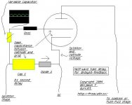
Step 1: Half-wave comes from Splitter stage at plate voltage of that stage and is placed to the proper grid voltage by Res 1.
Step 2: At the same time the capacitor is showing a signal on the cathode, which is also the same wave, but is very faint.
Step 3: The grid acts as a feedback to the cathode /internally/
and externally.
Step 4: When the plate is saturated by the cathode and grid is not supressing electrons, This time at which it is acting as a Tetrode, when the grid is supressing electrons it acts as a feedback path to cathode and the plate is as if it wasn't even there.
Step 5: the variable capacitor acts as a fine tune to the time at which it takes for the signal to pass back to the cathode and re-create the loop, essentially cancelling out a small amount of it's own signal.
I think that's about it, tell me what you think...
I think the only way I can describe it is that it is a threshold diode which turns into a Tetrode while the screen is energized.
Maybe this will supress noise, maybe it'll fry.
I have apsoloutley no idea how it would work nor made calculations or simulated it.
No, but you can delay the final signal while the original signal modifies it.
Step 1: Half-wave comes from Splitter stage at plate voltage of that stage and is placed to the proper grid voltage by Res 1.
Step 2: At the same time the capacitor is showing a signal on the cathode, which is also the same wave, but is very faint.
Step 3: The grid acts as a feedback to the cathode /internally/
and externally.
Step 4: When the plate is saturated by the cathode and grid is not supressing electrons, This time at which it is acting as a Tetrode, when the grid is supressing electrons it acts as a feedback path to cathode and the plate is as if it wasn't even there.
Step 5: the variable capacitor acts as a fine tune to the time at which it takes for the signal to pass back to the cathode and re-create the loop, essentially cancelling out a small amount of it's own signal.
I think that's about it, tell me what you think...
I think the only way I can describe it is that it is a threshold diode which turns into a Tetrode while the screen is energized.
Maybe this will supress noise, maybe it'll fry.
I have apsoloutley no idea how it would work nor made calculations or simulated it.
Attachments
No, but you can delay the final signal while the original signal modifies it.
Yes, that is called feedforward and is well known, also the problems with it.
What I originally commented is that as an amplifier always will have delay however small and feedback can not be corrected in any way to counter act that.
Regards Hans
I'm losing you at your premise.
I'm not an engineer, but in the derivations of basic feedback equations I've seen, the delay is assumed to be negligible. The conversion of high levels of low order harmonics to low levels of high order harmonics is a consequence of the feedback itself, and this conversion is independent of any delay and independent of the frequency. Now where delay DOES enter into things as a practical matter is in loop stability at very high frequencies, but that's not really relevant to the question of production of higher harmonics in the audio band. Even with zero delay, you'll still have those higher order harmonics.
Here is an idea for those who don't like the fact that normal error correction or negative feedback always ends up correcting the error after the fact. Thus creating higher harmonics, as the error in the error signal propagates endlessly around the loop.
I'm not an engineer, but in the derivations of basic feedback equations I've seen, the delay is assumed to be negligible. The conversion of high levels of low order harmonics to low levels of high order harmonics is a consequence of the feedback itself, and this conversion is independent of any delay and independent of the frequency. Now where delay DOES enter into things as a practical matter is in loop stability at very high frequencies, but that's not really relevant to the question of production of higher harmonics in the audio band. Even with zero delay, you'll still have those higher order harmonics.
/me looks stunned at SY as usual 
WHAAAAAA!!!!!???
All hail Holy and Wise SY!
I'm going to leave the whole thing as it is, TOO much for me!, glad however that I came up with "feedforward" in a matter of 2-3 hours...I bet any Phillips employee would have been proud to have me
WHAAAAAA!!!!!???
All hail Holy and Wise SY!
I'm going to leave the whole thing as it is, TOO much for me!, glad however that I came up with "feedforward" in a matter of 2-3 hours...I bet any Phillips employee would have been proud to have me
Problems in the design!
tubetvr said:
If you are concerned about feedback adding new distorsion products there are many solutions of which I can name a few:
1 Minimise distorsion before feedback is applied, (this is one of the main reason why tube amplifiers often have less of this problem then SS)
2 Minimise time delay trough the amplifier and feedback circuit
3 Increase feedback, if feedback is high enough then also higher order distorsion products will be soo low that they are not any problem, (Holcro?)
......
---------
Yes, I agree, these are more practical approaches.
Sy said:
The conversion of high levels of low order harmonics to low levels of high order harmonics is a consequence of the feedback itself, and this conversion is independent of any delay and independent of the frequency. Now where delay DOES enter into things as a practical matter is in loop stability at very high frequencies,
---------
I agree here also, the hope would be that one could apply higher gain stably to reduce the errors if the feedback delay were eliminated. On thinking more closely about my idea though I think this still can not be done. The dither signal is filtered out of the feedback, so is operating open loop for starters. The synchronous sampling also is a problem for noise since one can only get a single sample rather than averaging a bunch of them.
The "proto" design for all this was based on having two exactly identical amplifiers "A" and "B". The input signal to ampl. "B" would use the input signal plus a small linear predicted step from a differentiator. Amplifier "A" would have just the original input signal applied. Amplifier "B" would have a normal feedback loop for itself. Amplifier "A" would use the same feedback signal from "B" since it would be "just in time" rather than delayed for its input. The impossibility of building two exactly identical amplifiers led to the earlier described dither and sync. demod. idea for implimentation on a single amplifier. Obviously, however, the amplifier "B" in the proto design is still limited by stability considerations, so cannot have arbitrarily high gain to reduce errors to arbitrary smallness. So only the delay artifact can be canceled but not the errors from lack of open loop gain. So I guess we can scratch this idea. Hmmm... but maybe with feedforward...
Here is an idea for those who don't like the fact that normal error correction or negative feedback always ends up correcting the error after the fact.
Which is why bandwidth is ALWAYS limited a distinct amount in any well-designed amplifier. Limiting it reduces the HF signals that are delayed, such that they have no effect and the amplifier remains stable.
Tim
Yes that is true as long as the delay is neglible compared to the signal time period, it has however a lot of importance in linearised RF amplifiers but that is outside this discussion.The conversion of high levels of low order harmonics to low levels of high order harmonics is a consequence of the feedback itself, and this conversion is independent of any delay and independent of the frequency.
I think it is more easy to grasp if you talk about phase characteristics instead of delay as a constant delay is equal to phase changing continously with increased frequency. Normally amplifiers doesn't have significant constant delays but phase can anyway change as frequency increases. Example: if the delay is 100ns it will give 0.036 degrees phase lag at 1kHz, 0.36 degrees at 10kHz. 3.6 degrees at 100kHz and so on, normally this is neglible compared to the phas shift introduced by the high frequency poles in the amplifier.Now where delay DOES enter into things as a practical matter is in loop stability at very high frequencies,
As I tried to describe above the constant delay is not the problem but phase caracteristics are, an amplifier that never have phase changing close to 180 degrees, (preferably with some margin) will always be stable no matter what amount of feedback is applied, (it sounds more simple then it really is)I agree here also, the hope would be that one could apply higher gain stably to reduce the errors if the feedback delay were eliminated.
Which is why bandwidth is ALWAYS limited a distinct amount in any well-designed amplifier.
If you express it like that then most classic tube amplifiers are not well designed as they normally are bandwidth limited by the output stage and not the input stage.
I think it is better to say that "a well designed amplifier should have a bandwidth that is either; 1 wider then the applied signal OR if that is not possible 2 it should have its bandwidth limited by a low pass filter on the input in order for condition 1 to be fulfilled" This is more or less what Matti Otala and others after him came up with.
The reason why classic tube amplifiers have less problems then the early SS amps is that the many tube amps have wider bandwidth then the applied signal and therefore a bandwidth limitation is not necessary, for the early SS amplifiers it is different as they had very limited internal bandwidth and they where not bandwidth limited on the input and therefore produced different kind of distorsions, (TIM, DIM etc).
Regards Hans
If you express it like that then most classic tube amplifiers are not well designed as they normally are bandwidth limited by the output stage and not the input stage.
Well, open-loop, most classic tube amps are bandwidth limited by their compensation. And I don't think in general that they slew-limit; all the ones I've tested have a constant rise-time, not slew rate. Crowhurst made a big point of this in some of his articles. he was a big proponent of not trying to make the amp ultra-high bandwidth, and let first stage compensation be applied strongly enough to greatly reduce or eliminate the need for the lag compensation cap in the feedback network ("faking" a good transient response was his way of putting it). His arguments in that direction make great sense to me.
tubetvr said:If you express it like that then most classic tube amplifiers are not well designed as they normally are bandwidth limited by the output stage and not the input stage.
I never said it had to be limited at either end specifically. As far as the NFB is concerned, it doesn't make a difference. Electrically you'll burn much more heat shunting an HF parasite at 50W on the output than at .5mW on the input. However, many arrangements (esp. the OPT windup) still require an output damping network or two.
I think it is better to say that "a well designed amplifier should have a bandwidth that is either; 1 wider then the applied signal OR if that is not possible 2 it should have its bandwidth limited by a low pass filter on the input in order for condition 1 to be fulfilled" This is more or less what Matti Otala and others after him came up with.
Putting the BW limits outside of the NFB loop (i.e., at the input) will certainly keep phase shifts out of the system and avoid the respective LF distortion (HF too, but the harmonics fall outside the BW) near the extremes ("skirts" is it called?), where NFB is lower due to the reduced gain and thus distortion higher. This of course is compounded by saturation distortion in the OPT, for instance.
Perfectly fine for a well-equipped amp but if you have to make do with cheaper scrap iron (say, 30 to 15,000Hz rated) you don't have much choice.
Tim
Question
It seems that two different interpretations are possible of how the higher distortion harmonics are generated.
1) The falling open loop gain with frequency is simply unable to addequately suppress the inherent distortion generated in the amplifier, mainly in a single pass thru the amplifier.
2) The feedback loop causes the correction signal to repetitively cycle around the loop, each time causing a higher order of distortion to the previous residual distortion.
Which is the correct picture? Or both?
If #2 is primarily the problem, then it would seem that a scheme such as mentioned earlier (identical "A" and "B" amplifiers etc.) would have some merit since the signal would only pass thru the "A" amplifier once.
(of course, it still does loop around in the "B" amplifier, so maybe not that much merit.) But might be possible to design a scheme that has only a single pass loop. (Might look like feedforward I guess)
Indeed it does loop around, say an amp has 5% 2nd H, 2% 3rd H and nothing else, with 20dB NFB it might drop to .5% 2nd H, .2% 3rd, plus distortions of the harmonics: .025% 4th, etc. (You can figure the intermodulation distortions yourself. ) If it's more like 6dB NFB however, you would have 2.5% 2nd, 1% 3rd, .125% 4th, etc. We all know that higher harmonics are considered increasingly unpleasant, odds in particular, so you can clearly see that just a hint of NFB will make it sound much worse than a larger amount.
Due to the inevitable phase shifts and delays in the system, a pulse would indeed bounce back and forth, but it would take a terrible design to have this readily apparent on the scope. A good design has the system damped and under control, hence the pulse is severely attenuated in very few iterations.
Tim
) If it's more like 6dB NFB however, you would have 2.5% 2nd, 1% 3rd, .125% 4th, etc. We all know that higher harmonics are considered increasingly unpleasant, odds in particular, so you can clearly see that just a hint of NFB will make it sound much worse than a larger amount.Due to the inevitable phase shifts and delays in the system, a pulse would indeed bounce back and forth, but it would take a terrible design to have this readily apparent on the scope. A good design has the system damped and under control, hence the pulse is severely attenuated in very few iterations.
Tim
Single pass error correction !!
OK, what goes around, comes around the loop. Then here is a new horizon for feedback error correction. I'm dreaming this one up while still half asleep. Here is the idea. An error correction system that only looks at the change in the signal input and change in the signal output to perform its correction process on, so as to only process things once (well assuming the signal changes). Hence, hopefully no repeated/compounded distortion possible. Here is the plan:
A single high frequency (sine wave, above audio freq.) dither signal of small but constant amplitude is added to the input signal. At the output of the amplifier, the dither signal is synchronously detected (continuously in this case so no S/N problem) and its amplitude is compared to a reference. The error in its amplitude is used to control a multiplier circuit at the amplifier input so as to bring it back into calibration at all times. The multiplier will effectively be controlled so as to produce unity overall gain at all points in a waveform, thus providing compensating "pre distortion" of the input signal. (Analyzing this can lead to some confusion since the multiplier acts on the previous increments of the signal, but I think as long as the output to input deltas are a constant ratio this has to integrate to a linear gain)
The output of the amplifier would of course need a notch or low-pass filter to remove the dither frequency before sending it on to a speaker.
An alternative approach might be to dispense with the dither signal and just take the derivatives of the input signal and the output signal and compare their ratio, then control the multiplier based on that. Would have some problems with a stationary signal though, so would need a servo like (low freq.) conventional neg. feedback control too.
I couldn't help but notice some of the parent poster comments are quite the same as to what is going on in this schematic:
http://digilander.libero.it/paeng/seidel.htm
http://digilander.libero.it/paeng/seidel.htm
Hmm, interesting. Modulating the amplifier's instantaneous gain based on a reference signal (whose frequency is faster than the band of interest). It would reduce down to NFB anyway however because when you reach clipping, an increase in input voltage will not follow with an increase in output voltage. In the end you'd need an amp much faster (due to delay in the dither) and complicated (although I suppose the gain control could be provided by a heptode or dual control pentode input stage). Simple is often best so you're probably better off without the Rube-Goldberg dither signal stuff. 
What if you null input with output, getting a difference signal (total distortion: frequency response, phase, THD, etc... so you'll have to be careful with band limiting of this distortion seperator), then mix this signal out-of-phase with the input? Simple dif. amp and mixer, no complicated dither, but still boils down to NFB.
Tim
feedforward
re: Layberinthius
The Seidel patent is the classic feedforward scheme for RF signals. Some other nice articles on feedforward (some applicable to audio) can be found in:
"Feedforward Error Cancellation" by Ronald M. Bauman in The Audio Amateur 4/89 page 15
"Audio Design leaps forward" by Giovanni Stochino in EW+WW October 1994 page 818
"Feedforward Error Correction in Power Amplifiers" by Vanderkooy and Lipshitz in JAES 1980 January vol. 28, no 1/2 page 2
also see JAES vol. 44 no. 9 1996 Sept. page 721 Danyuk and Pilko
JAES vol. 29 no. 7/8 1981 July pg 503 Hawksford
JAES vol. 29 no. 1/2 1981 Jan. pg 27 Hawksford
My single pass error correction idea (in previous post) however is not using feedforward (at least not yet!) but is a weird type of conventional feedback.
Just as a note, for those who were wondering how one is going to be able to perform an arithmetic multiply function in a tube system, this is no problem at all. The beam deflection tubes (6AR8, 6JH8, 6HW8, 6ME8, 7360 ...) can readily be configured to do this. However, I just bought up the entire World supply of them! (all 5 of them!)
re: Tim
"What if you null input with output, getting a difference signal (total distortion: frequency response, phase, THD, etc... so you'll have to be careful with band limiting of this distortion seperator), then mix this signal out-of-phase with the input? Simple dif. amp and mixer, no complicated dither, but still boils down to NFB."
This certainly would be like conventional feedback, except using the error signal to control a multiplier (or mixer), maybe it overcomes the large gain requirement of conventional NFB, don't know. I've never seen anything using the multiply scheme, so I don't know how it compares in detail to conventional NFB. Might be worth some effort to do the math or simulate it to see how it performs.
My additional factor of using the "incremental" gain
error for control of gain is in hope of eliminating the "around the loop" compounding of the order of the distortion products. But this needs checking or simulating too. No doubt either scheme using a multiplier (or mixer) will have distortion products that depend on loop gain, I'm just trying to prevent the repeated "distortion of distortion" looping that would make high harmonics.
By the way, a multigrid mixer could generate the dither (osc.) signal too (besides doing the multiply), much as many superhetrodyne receivers did economically in one mixer tube.
The tube would need to be fairly linear regarding the actual signal input grid, but the gain control grid doesn't really need to be all that great, just affects loop gain. (The beam defl. tubes are actually overkill, don't need more than one quadrant multiplication) Might want to use two multigrid mixer tubes in a LTP config. to get linear signal input though. The beam defl. tubes can accomplish the same LTP config. in a single tube.
Um, don't you just want the dither superimposed on the audio, not modulated in? G4 will AM modulate the local oscillator:
I think you would still get the looping effect because the dither must correct for itself. (Note that, if the dither control loop has low gain, it won't correct the distortions as effectively, just like normal NFB.) The only difference is the dither is being corrected for as though you were sampling the output, as opposed to continuous "sampling" with standard loop NFB, and the dither rather than the audio itself is being corrected. Same distortion-reducing effect of course (hence why you thought of it ) since it's going through the same amplifier.
Huh... you'll get IMD with the dither and audio signals. I don't think that would be corrected because you aren't looking for IMD products, only the fundamental dither signal. Or does the predistorted signal produce negative IMD which cancels with that of the amp?
Tim
I think you would still get the looping effect because the dither must correct for itself. (Note that, if the dither control loop has low gain, it won't correct the distortions as effectively, just like normal NFB.) The only difference is the dither is being corrected for as though you were sampling the output, as opposed to continuous "sampling" with standard loop NFB, and the dither rather than the audio itself is being corrected. Same distortion-reducing effect of course (hence why you thought of it
) since it's going through the same amplifier.Huh... you'll get IMD with the dither and audio signals. I don't think that would be corrected because you aren't looking for IMD products, only the fundamental dither signal. Or does the predistorted signal produce negative IMD which cancels with that of the amp?
Tim
hither and dither and IMD
Yes, the dither needs to be superimposed on the signal input, not modulated against it. The oscillator would need to be built on the signal input grid rather than on the gain control grid (as in superhets) in order to do a sumation. At least I think that might work. But, probably is a lot safer to do as a seperate oscillator tube and just sum them, since we are trying to do HiFi here. Might radiate dither signal out the input cable too with an all in one scheme.
As for IMD from the dither signal and audio signal, I would hope to avoid this by the high frequency of the dither signal such that difference freqs. would still fall outside the audio band. (Sum freqs. would really be outside) Also, the dither signal, by the very nature of testing gain at an instantaneous operating point, would have to be a small level signal, so should be relatively safe.
Chapter 2:
Looking at the case of limited loop gain, in a normal NFB system the finite gain simply fails to deliver quite enough error correction signal, so some error remains in the output level. And since conventional NFB compares absolute values of input to output, it will notice the error subsequently and try to correct it again, causing effects to recirculate around the loop.
With the incremental gain correction control idea (using dither), I think it may be a question of just getting the CORRECT loop gain to fix the problem exactly, not a problem with lack of infinite gain. Also there is still the delay problem, but should be minimal if system speed is faster than the signal as in a well designed conventional NFB system. (obviously, amplifier saturation problems are another matter, no amount of compensation of the input will fix that)
But notice that in a conventional NFB system that absolute values of input and output are compared, so any residual uncorrected error gets noticed and recirculates again with later correction. But here, with the dither design, only the present operating gain is of interest to the correction system. Previous errors are un-noticeable by the error detection system. (ie. the output could be way off and the error detection doesn't care one bit as long as the present dither signal is coming thru with the correct level, just cares about present system gain) The correct absolute value of output signal is dependent simply on natural integration of all the controlled gain incremental changes of the signal.
So errors in the correction loop gain will show up first order as residual, but non recirculating, distortion, and second order as gain drift and maybe offset drift. A low frequency servo control NFB loop can probably be implemented to fix these second order effects.
Chapter 3, after I do some simulations to see if this is all true or just BS.
- Status
- This old topic is closed. If you want to reopen this topic, contact a moderator using the "Report Post" button.
- Home
- Amplifiers
- Tubes / Valves
- Time advanced error feedback correction