Hi,
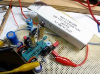
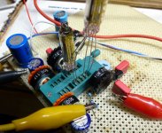
I started my next build with some 5672 and 5678 subminiature tubes. The whole idea is to build an all tube headphone amplifier to listening to music and to play guitar. I choose the 5678 and 5672 tubes because of the low current heater and the low voltage required. I want to use a high Z headphone that had no use for me until now.
Here it is:

it has an impedance of 4k ohms at each side, so 8k in series. I'm not sure about wattage, but it's the magnetic type with *i guess* 40 wire coil.
About the Amplifier:
The tubes I'm using are direct heated and to complicate things further I'm willing to use the filaments in series to match the Li-ion battery voltage. The B+ voltage comes from a MAX1771 SMPS, which should deliver 65V at 5mA, resulting in aproximately 100mA current at 3.7v, with the heaters it ends up at 150mA.
The schematic>

The schematic was based on my current experiments, which used 5v from a wall wart. But I thing the main change would be removing the 22 ohms resistor.
I drawed the load lines for the 5678 and ended up at 120k for the Rp, 100k for the g2 and -1.6v at the grid. As you can see in the schematic, the measured voltages were a little different, and there are some difficulties that I found:
Wich cathode voltage should I use in my calculations? The positive side of the filament, the negative or the mean value?
Are there any other ideas on how to bias these tubes other than with a huge grid leak resistor? I'm not sure about adding a C battery.
I think the second tube is OK, because the cathode is between 2.6v to 1.3, which lies "near" 1.6v. The 5672 datasheet specifies a grid bias of -6.5v. I'm guessing it won't be a problem. The first stage is more difficult, since one side of the filament is grounded.
My last question regards the headphone connection. In detectors the headphone goes between the power tube plate and the high voltage, as an OT. I also saw some schematics using the current arrangement with the capacitor and a resistor at the 5672 plate. Any idea about what would be the best configuration?
I'm posting here cause I know there are a lot of guys that really understand how tubes work, and maybe have an idea of what to do with direct heated tubes. The books I read where not focusing on this topic, maybe you have some suggestions.
This amplifier should also be applicable for guitar, another reason to use more tubes, but in the end it will also require a gain control, other than the volume I already added. My oscilloscope showed that a 0.2v sine resulted in a 5v peak after the first stage and distortion right before the 5672. I made a quick video, using the headphone near the camera>
Subminiature 5678 5672 amplifier - YouTube
Thank you for your attention!
I started my next build with some 5672 and 5678 subminiature tubes. The whole idea is to build an all tube headphone amplifier to listening to music and to play guitar. I choose the 5678 and 5672 tubes because of the low current heater and the low voltage required. I want to use a high Z headphone that had no use for me until now.
Here it is:
it has an impedance of 4k ohms at each side, so 8k in series. I'm not sure about wattage, but it's the magnetic type with *i guess* 40 wire coil.
About the Amplifier:
The tubes I'm using are direct heated and to complicate things further I'm willing to use the filaments in series to match the Li-ion battery voltage. The B+ voltage comes from a MAX1771 SMPS, which should deliver 65V at 5mA, resulting in aproximately 100mA current at 3.7v, with the heaters it ends up at 150mA.
The schematic>
The schematic was based on my current experiments, which used 5v from a wall wart. But I thing the main change would be removing the 22 ohms resistor.
I drawed the load lines for the 5678 and ended up at 120k for the Rp, 100k for the g2 and -1.6v at the grid. As you can see in the schematic, the measured voltages were a little different, and there are some difficulties that I found:
Wich cathode voltage should I use in my calculations? The positive side of the filament, the negative or the mean value?
Are there any other ideas on how to bias these tubes other than with a huge grid leak resistor? I'm not sure about adding a C battery.
I think the second tube is OK, because the cathode is between 2.6v to 1.3, which lies "near" 1.6v. The 5672 datasheet specifies a grid bias of -6.5v. I'm guessing it won't be a problem. The first stage is more difficult, since one side of the filament is grounded.
My last question regards the headphone connection. In detectors the headphone goes between the power tube plate and the high voltage, as an OT. I also saw some schematics using the current arrangement with the capacitor and a resistor at the 5672 plate. Any idea about what would be the best configuration?
I'm posting here cause I know there are a lot of guys that really understand how tubes work, and maybe have an idea of what to do with direct heated tubes. The books I read where not focusing on this topic, maybe you have some suggestions.
This amplifier should also be applicable for guitar, another reason to use more tubes, but in the end it will also require a gain control, other than the volume I already added. My oscilloscope showed that a 0.2v sine resulted in a 5v peak after the first stage and distortion right before the 5672. I made a quick video, using the headphone near the camera>
Subminiature 5678 5672 amplifier - YouTube
Thank you for your attention!
Last edited:
What's wrong on the grid leak polarization on the preamp tube? This was standard practice on dry cell battery radio tubes. On my amplifier based on DAF96 and DL96 tubes, the DAF96 preamp tube has a 10M grid leak resistor as specified by the manufacturer, and it works just fine. To get the -5V output tube negative bias supply I applied another common trick of the tube battery radio age: the negative bias voltage is derived from the B+. It is a very simple arrangement: the negative terminal of the anode supply and the negative terminal of the filament supply are tied togheter trough a resistor (the value on battery radio was usually 560 ohms; on my 4 tubes amplifier is 750 ohms). The common ground is the filament negative terminal. This means that all the B+ current must travel trough the resistor to close the anode supply circuit, and therefore the negative terminal of the anode power supply becomes more negative than the common ground. This negative supply voltage is then feed to the grid of the output tube by a 1M resistor.
I found that the DAF96 works best when triode connected, but the gain is significanty reduced. Haven't tried yet the 5672 as output tube but I will eventually substitute it to the DL96 to check out the sound. It is almost the same tube, electrically. The puny sub-watt tubes are a good match with a high efficiency speaker. The volume of my amplifier is just about the same as a modern computer speaker, perfect for casual listening, but the sound quality is near to my bigger living room tube amplifier. No need to limit this circuit to headphone uses.
And it turns on/off instantly. When I first build it, I may have turned it on and off 20 times in a row just for the fun and amazement. As practical as a solid state amplifier but the sound is clearly from a tube.
My last question regards the headphone connection. In detectors the headphone goes between the power tube plate and the high voltage, as an OT. I also saw some schematics using the current arrangement with the capacitor and a resistor at the 5672 plate. Any idea about what would be the best configuration?
No personal experience here, but fooling around with load lines on the 5672 triode curves makes me think that you should try putting the 8K coil impedance directly in series with the anode for a good match. As long as the diaphragms don't bottom on the magnets, you should get nearly 40mW of relatively clean output that way. Grid bias will need to be around -4V for 5mA of idle current at 60V on the anode and G2.
FYI: According to Langford-Smith, directly heated tube data is referenced to the negative end of a DC-operated filament.
Last edited:
Hi, the headphone is indeed made of bakelite with the metallic membrane. It was probably for radio. I could't find much information about them, other than how to remagnetize them.
pcan thank you for the information, I will take a look at it. I think it is possible if I use different batteries, one at the common ground and the second grounded through the resistor.
The thing with the grid leak is that for the 4.7M in the schematic I only got -0.43v. I would need almos 20M to achieve the desired -1.6v.
Good to know that the reference is the negative side. Unfortunately I don't have a high impedance meter to confirm the bias. Even the low cost oscilloscope I'm using may influence the readings in this case. This makes the grid leak bias harder check.
I'm aware that the headphones aren't the best for listening music, but for guitar they sounded OK. I still can add a real transformer later.
Looking for other schematics and builds I found this one>
http://www.diyaudio.com/forums/tubes-valves/234898-micro-amp-all-tube-direct-heated-portable-fits.html
I'm not sure where to find these transformers, but they look like the normal 1k to 8 ohms transformers available at radioshack. Not sure if they are good for the voltages I'm using, or what to expect in terms of bass. Probably they are for high frequency stuff.
Last edited:
Hi,
My last question regards the headphone connection. In detectors the headphone goes between the power tube plate and the high voltage, as an OT. I also saw some schematics using the current arrangement with the capacitor and a resistor at the 5672 plate. Any idea about what would be the best configuration?
Before getting into amps I built a few battery tube radios with a variety of tubes and as I could find them "authentic" old parts. The main reason for the cap/resistor arrangement is to keep the B+ voltage off the headphones. They are not well insulated and in some cases the signal voltage can appear on exposed metal studs.
BTW, as stated elsewhere, these types of headphones were designed to be incredibly sensitive over a very narrow frequency range corresponding to voice and code tone ranges. They have absolutely no low frequency response and a rapid cutoff on the high end.
High impedance horn speakers with larger diaphragms exist. They still sound tinny, but at least could reasonably reproduce some range of music. You can find them on E-Bay, but working ones are $$$$.
I an experimenting with these little tubes for two projects. One is a guitar preamp, or say 6 of them that will go inside the electric guitar. Graph Tech Ghost Pickups, one per string. Power is a 7.2 volt RC car battery. They are common, cheap and easy to charge.
Ghost Pickups - Guitar
I have been experimenting with vacuum tube music synthesis, in particular a vacuum tube Moog style ladder filter. It's relatively simple to make one with standard size tubes, but that won't fit in a Eurorack sized module, or run from Eurorack power.....so the tiny tubes are a possibility.
I made a simple test board to evaluate some tubes. I used one or two silicon diodes to raise the filament 0.7 or 1.3 volts above ground. Simple, effective, but wastes power. The schematic you linked does this too. All filaments are wired in parallel and fed from a step down converter off of 12 volts. I think 6 tubes in series would be too hard to bias, but I may try it later.
Long term I will probably use a negative voltage generator chip since there is virtually no current drain. The LM2664 will make -5 volts and eat 1/2 a milliamp with no load.
I had a similar pair of headphones when I was a kid. I believe they came from a WWII vintage Army field radio. Yes, they would shock you when fed by a 67.5 volt battery on a sweaty hot Florida day.
You can't measure the grid leak voltage with any real meter. An old VTVM has a 10 or 11 megohm input resistance. The cheap Chinese digital meters of today are about 1 megohm. That gets put in parallel with your grid leak resistor when you try to measure the voltage. Just tweak the resistor value for best tone, or lowest distortion. Whichever you prefer.
Ghost Pickups - Guitar
I have been experimenting with vacuum tube music synthesis, in particular a vacuum tube Moog style ladder filter. It's relatively simple to make one with standard size tubes, but that won't fit in a Eurorack sized module, or run from Eurorack power.....so the tiny tubes are a possibility.
I made a simple test board to evaluate some tubes. I used one or two silicon diodes to raise the filament 0.7 or 1.3 volts above ground. Simple, effective, but wastes power. The schematic you linked does this too. All filaments are wired in parallel and fed from a step down converter off of 12 volts. I think 6 tubes in series would be too hard to bias, but I may try it later.
Long term I will probably use a negative voltage generator chip since there is virtually no current drain. The LM2664 will make -5 volts and eat 1/2 a milliamp with no load.
I had a similar pair of headphones when I was a kid. I believe they came from a WWII vintage Army field radio. Yes, they would shock you when fed by a 67.5 volt battery on a sweaty hot Florida day.
I would need almos 20M to achieve the desired -1.6v.
You can't measure the grid leak voltage with any real meter. An old VTVM has a 10 or 11 megohm input resistance. The cheap Chinese digital meters of today are about 1 megohm. That gets put in parallel with your grid leak resistor when you try to measure the voltage. Just tweak the resistor value for best tone, or lowest distortion. Whichever you prefer.
Attachments
A couple of other random thoughts specifically regarding high-impedance headphones:
- In the best ones the metal diaphragm is very thin and can be buckled if over-driven, permanently ruining it.
- If you find you like the sound, the the "Cadillac" of high-impedance phones goes by the military designation "H43 B/U". I think these were built to withstand a shrapnel hit, and have ear cushions that basically cut out the world and conform to pretty much any reasonable size of head and ears. There always seem to be a few for sale on the usual sites for reasonable prices.
good to know! Mine is made of a thicker metal piece and with the 5672 was already a little too loud. Now that I know that it's not that safe I think I'm gonna stay with the current output stage.
Does it helps to add an inductor in parallel with the 20k resistor? I saw some pictures where the winding was around the plate resistor, like this:
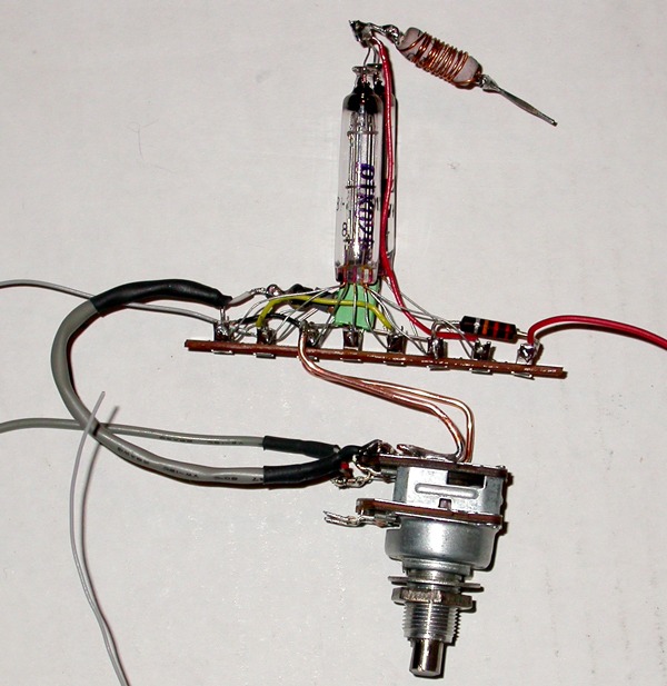
in this case it was only a 180 ohms resistor in series with the OT.
Tubelab, I'm thinking of using a similar strategy. I'm not sure if I can use the MAX1771 as step-up and negative supply at the same time, but there are chips where this implementation would be possible. The ICL7660s has this option, but the switching frequency is in the audio range (10 to 30 khz).
I also have some 5676 triodes, which only require 12mA. I could use 8 of them, 4 em parallel, in series with the 5672 to achieve the 3.75v of the battery. I guess that would make a nice high gain amplifier running at 65v (I think they have a mu of 25).
Does it helps to add an inductor in parallel with the 20k resistor? I saw some pictures where the winding was around the plate resistor, like this:
in this case it was only a 180 ohms resistor in series with the OT.
Tubelab, I'm thinking of using a similar strategy. I'm not sure if I can use the MAX1771 as step-up and negative supply at the same time, but there are chips where this implementation would be possible. The ICL7660s has this option, but the switching frequency is in the audio range (10 to 30 khz).
I also have some 5676 triodes, which only require 12mA. I could use 8 of them, 4 em parallel, in series with the 5672 to achieve the 3.75v of the battery. I guess that would make a nice high gain amplifier running at 65v (I think they have a mu of 25).
- Status
- This old topic is closed. If you want to reopen this topic, contact a moderator using the "Report Post" button.
- Home
- Amplifiers
- Headphone Systems
- Battery powered Subminiature tube amp for high Z headphones