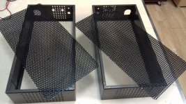
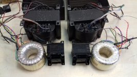
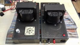
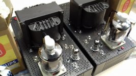
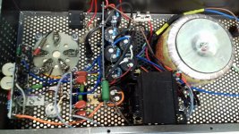
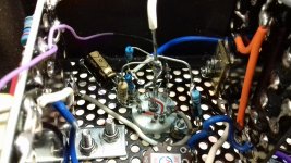
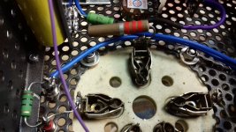
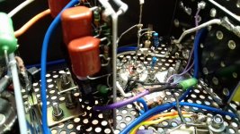
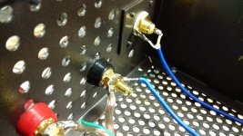
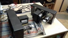
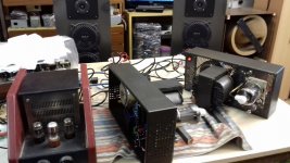
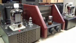
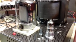
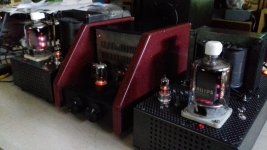
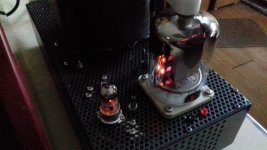
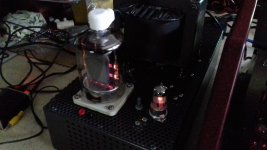
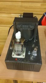
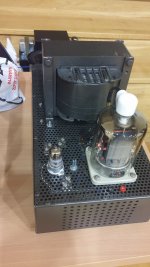
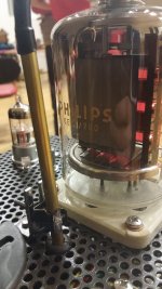
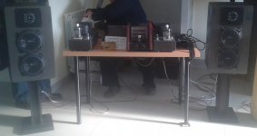
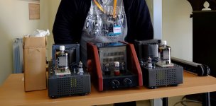
Simple mono-blocks designed for presentation at Triode Festival 2017-Krizevci (in Croatia) with triode connected QE08/200 in the output stage of the class A1, and D3a also triode connected in the driver and the voltage amplification stage.
Attachments
-
 20170327_193244_1024_576.jpg198.2 KB · Views: 570
 -
 20170328_120412_1024_576.jpg142.4 KB · Views: 553
 -
 20170328_120432_1024_576.jpg104 KB · Views: 537
 -
 20170331_102727_1024_576.jpg166.7 KB · Views: 561
 -
 20170331_133215_1024_576.jpg169.2 KB · Views: 529
 -
 20170407_081321_1024_576.jpg195.1 KB · Views: 236
 -
 20170407_081332_1024_576.jpg199.8 KB · Views: 205
 -
 20170410_164923_1024_576.jpg158 KB · Views: 226
 -
 20170415_105020_1024_576.jpg130.6 KB · Views: 284
 -
 20170415_105048_1024_576.jpg143.9 KB · Views: 332
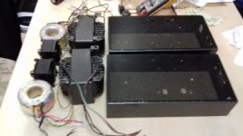
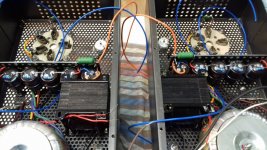
Continuation of works:
Attachments
-
 20170418_102559a.jpg385.8 KB · Views: 270
 -
 20170418_102607a.jpg344.1 KB · Views: 186
 -
 20170418_191849a.jpg294 KB · Views: 145
 -
 20170418_191857a.jpg271.8 KB · Views: 158
 -
 20170418_191913a.jpg273.3 KB · Views: 146
 -
 20170418_191924a.jpg314.8 KB · Views: 151
 -
 20170418_192009a.jpg307 KB · Views: 138
 -
 20170418_192017a.jpg277.6 KB · Views: 141
 -
 20170419_121116_1024_576.jpg120 KB · Views: 147
 -
 20170419_121121_1024_576.jpg134.3 KB · Views: 160
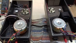
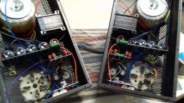
More pictures:
Attachments
-
 20170419_121130_1024_576.jpg96.5 KB · Views: 167
 -
 20170419_183025_1024_576.jpg140.1 KB · Views: 200
 -
 20170419_183045_1024_576.jpg135.4 KB · Views: 204
 -
 20170419_183056_1024_576.jpg115.2 KB · Views: 203
 -
 20170419_183102_1024_576.jpg104.6 KB · Views: 207
 -
 20170419_183154_1024_576.jpg122.2 KB · Views: 188
 -
 20170419_183209_1024_576.jpg115.1 KB · Views: 184
 -
 20170419_183205_1024_576.jpg109.7 KB · Views: 153

Good luck for the fest. It looks like a nice budget build to me, but it might kick some ***.
If you don't mind answering, do you have triode curves for the QE08/200?
What is the value of B+. Does G2 handle it?
If you don't mind answering, do you have triode curves for the QE08/200?
What is the value of B+. Does G2 handle it?
Last edited:
I did not find the curves and the data for triode connection for tube QE08/200 on NET, so I came to the required information with experiment and measuring. Thus I have come up with the data on the internal resistance of the triode connection by the formula Ri = delta Ua / delta Ia with constant G1 voltage .
In that case, it was ~ 600 Ohma (Ua between 400 and 500V with steps ~10V) and according to the empirical recommendation it is necessary to adjust the primary impedance Rload between 3xRi and 7xRi (in triode smaller Rload gives higher output power with higher distortion and higher Rload less power And smaller distortion).
Owning already-finished output transformers was actually a choice of output transformer in this case.
QE08/200 well tolerated G2 up to 500V in a triode connection (even in UL-connection!) and has no trace of overheating (Ig2 ~ 5-15mA).
Tube is very, very linear, and in fact I have not met up to now a more linear tetrode or pentode triode connecteed!
Last edited:
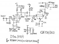
Schematics:
Bravo, Devorin!
I've built a SE EL803S>RS1003 amp based on your schematics and sounding awesome! Thanks!
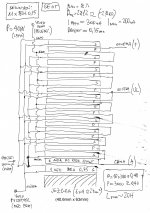
Output transformers data:
Hi Davorin.
Which EI laminatios did you use? EI120 or bigger?
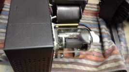
EI120x60 is the simplest standard size, but the core used is from ERICSON's old telephone switchboard. The sheets are thick ~ 0.22mm, the middle pillar is 40.6mm wide and the thickness of the package is ~ 63-64mm. The core was wound with a DC choke that was used in a rectified 48V voltage filter at a frequency of ~ 400Hz. The hole ("window") on the core is larger than the standard EI120 core (which allowed me to "comfortably" accommodate a large number of wound sections!), but I think similar results would be obtained with the mentioned standard EI120 core.Hi Davorin.
Which EI laminatios did you use? EI120 or bigger?
Yes, but not for triode connection!
this tube likes low grid leak resistors....
what cathode current did you run this tube? plate voltage?
what cathode current did you run this tube? plate voltage?
The PHILIPS transmitter tube QE08/200 is designed for operation at relatively low voltage (max-825V!). The factory data does not have curves for triode connection, and since I could not find them on NET, I had to experimentally determine the initial output settings for the A1 SE-audio amplifier class.
Available data indicate that the maximum voltage for G2 (in tethrode!) can be ~ 350V, but in a triode connection, the tube is stable at Ua-Ug2 of 500V! The value of the G1 leakage resistor has been problematic, and for stable operation, it is necessary to keep a relatively low value compared to the normal values, at least when using a fixed negative bias. With values of ~ 50 kOhms (and larger ones, especially!), there would have starteed a backward emission and a gradual increase in current through the tube, which would ultimately lead to self-destruction of the tube. The limit value of the G1 resistor stability ranged around ~ 45kOhma, but for stable, safe and long-term operation, it would need to use lower values.
Although the electronics are foreseen for permanent work at anode dissipation of Pa ~ 100W (in triode connection probably more!), to prevent longer working life of the tube, I decided not to go with dissipation greater than Pag2 ~ 80W, which with voltage from Ub ~ 450 -460V results is a current of Ik ~ 175mA. Existing output transformers can expect an output power of ~ 20W )more for maximum power!) but in practice the usable part is smaller (parametar is distortion up to ~ 2%).
The low value of the G1 resistor requires low internal resistance of the driver stage (or more excitation power), so the choice of driver tube is limited. The intention to use the tube D3a-triode connected with its small internal resistance (Ri ~ 1,9kOhma) and high gain (~ 77x in ideal conditions, and in practice a little lower!) which excludes the need for more tubes.
Ik~175-185mA
Uak~455-465V
Pdis~80-85W
Pout~20-22W
Ik~175-185mA
Uak~455-465V
Pdis~80-85W
Pout~20-22W
thanks, just as i expected.......
- Status
- Not open for further replies.
- Home
- Amplifiers
- Tubes / Valves
- QE08/200-D3a Se-ClassA-Triode connected