Happened to read this paper in western electric archive where it explain in clear what the Engineers found and how it transit into WE Harmonic Balancer.
https://ia600306.us.archive.org/34/items/bstj34-6-1265/bstj34-6-1265.pdf
https://ia600306.us.archive.org/34/items/bstj34-6-1265/bstj34-6-1265.pdf
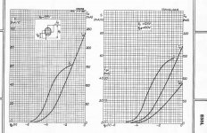
Seems that most attempts to use the WE Harmonic Balancer technique (P-P case considered here) only work for a limited range of signal amplitude. Which is not surprising if you look at the typical gm curve for tubes! S shaped. (1st pic)
At low amplitude the gm curve is curving upwards, indicating greater than square law V to I (gm being the 1st derivative of the V to I formula, so gm rule is 1 power less, so greater than 1.0 power here). At high signal level the gm curve is bending over, indicating less than square law V to I (so gm rule now less than 1.0 power here). So one WE HB fix will not work over the full range.
For class AB (P-P) the overlapped conduction region can be optimized so the expansive and compressive regions nearly compensate, until the class B region is reached, then compressive mode will dominate.
Class A will be dominated by varying amounts of compressive dist. The WE HB only tunes out one specific level of compressiveness. So falls short over the full signal region for power output. Useful for signal level stages though.
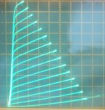
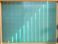
One does have another option for power fortunately (below, 2nd pic and 3rd pic, constant gm Twin/Crazy drive, 3rd pic is input V to I output):
At low amplitude the gm curve is curving upwards, indicating greater than square law V to I (gm being the 1st derivative of the V to I formula, so gm rule is 1 power less, so greater than 1.0 power here). At high signal level the gm curve is bending over, indicating less than square law V to I (so gm rule now less than 1.0 power here). So one WE HB fix will not work over the full range.
For class AB (P-P) the overlapped conduction region can be optimized so the expansive and compressive regions nearly compensate, until the class B region is reached, then compressive mode will dominate.
Class A will be dominated by varying amounts of compressive dist. The WE HB only tunes out one specific level of compressiveness. So falls short over the full signal region for power output. Useful for signal level stages though.
One does have another option for power fortunately (below, 2nd pic and 3rd pic, constant gm Twin/Crazy drive, 3rd pic is input V to I output):
Attachments
Last edited:
If we look at it as a full system, then the non linearity of the gm might somehow minimise by the inverse non linearity of the driver stage. The square law does work on the middle part of the gm curve meaning the harmonic cancellation works within the useful music range but no so well at the extreme power.
We might be interested in the tonality of the first 1-2 watt which encompasses the harmonic profiling of SE design. Peak power mainly lies with bass peak but there's so much distortion there anyway. Actually what I'm more interested in is the reduction of IMD. In my experience with SE, the clarity collapse with complex music where everything mush together somehow. This I believe might be the result of high IMD.
On the side note, some had experiment with adding a eg. 2ohm resistor to mimick the low damping factor of SE but fail. SE works by varying the output impedance to pass power whereas balance output swing only the current but tends to keep the output impedance constant. And I'm talking about DHT only. Back emf from speakers are better isolated thus appearance dynamic seems more powerful as compare to a parallel SE of similar power.
The WE HB works for correcting compressive distortion (at least as normally used).
The square law portion of a tube gm curve would be expansive in SE. (it can sum to constant gm in overlapped class A P-P, but usually still becomes compressive at the peaks due to the gm rollover dominating.)
So the WE HB is useful for class A P-P mainly.
By the way, it is much easier to see how the WE HB works in the usual analog/time domain than the frequency domain. Consider a LTP with a CCS tail. At the signal peaks, the tail voltage pulls up, due to the turning off tube being reluctant to give up current to the turning on tube. At the same time, the turning on tube is typically reaching the gm rollover region, so becoming net compressive. By adding a selected tail resistance, the tail current can increase slightly at the peaks, from the tail voltage variation. Just enough to increase the gm slightly to cancel the gm rollover effect. So the compression is flattened out. (Just one paragraph to explain, no 20 pages!)
SE is a tricky beast. As you said, output impedance variation along with tube harmonic distortion. Both tending to give 2nd harmonic that sums. (there is also some 2nd H permeability variation in the OT besides)
If I were going to experiment with something like the WE HB for SE, I would use a balanced OT. With the SE Triode on one primary side and a complementary current source (P-P complementary driven pentode) on the other xfmr side. (nominally, not exactly, summing to constant tail current for the two cathodes summed.) Then the tail current below them could be modified with a selected tail resistor to flatten out the gm sum, hopefully reducing the IM dist. There would still be output impedance variation from the triode side, like SE. (which will probably still contribute to some IM dist. )
I've heard comments that this scheme does not sound quite like SET though. Probably half as much 2nd harmonic as SET. You could try a lower than usual primary Z to increase the 2nd H back up I guess.
Last edited:
I think DHT PP is fine by its own if implemented carefully. Every distortion is bad be it even or odd. What we seek should be reducing it as far as we can go with the intrinsically linear device (tubes) rather than depending on feedback. For those that we can't remove, WEHB circuit will be useful to fine tune the HD profiles for least subjective objection.
Since we are on this topic of WEHB, can I seek your view on its implementation in WE86 amp? I see that the common cathode resistor is a 570R wire wound type with tapping to split it into 60+510R. From there a WE ultrapath cap connects the 560R to B+ and a 1uF connects the 60R (at the 300B cathode) to the grid. What I see from here is the grid will "float" together with the moving common cathode therefore maintaining a constant Vgk. It's only the Plate voltage that is "compressing" due to the common unbypass 60R. Knowing that WEHB works on the principle of frequency modulation eg. f+2f for cancellation, where did the injection of 2f comes from?
So my question, many posts before stated the even harmonics are fed into the grid circuit but what I deduce infact it's injected in the plate circuit. This is similar to adding a common resistance at B+ before the OPT? Is this correct?
In other word to implement WEHB properly, we need to couple grid and cathode constant while varying only the plate?
Looks like the proper WE name for this was the Harmonic Equalizer. The Balancer thing seems to be a later corruption of the name. Many more Google hits on WE Harmonic Equalizer.
I couldn't make heads or tails of the WE86B schematic. The WE92A schematic (below) seems to use the WE HE. Although, I don't see how it could work at all with the OT CT bypassed to ground. It needs a series resistor between the OT CT and B+ to pick up the common mode signal with the odd harmonics. Then that gets transferred to the cathode or grid circuits. Not making sense actually in their schematic.
Here is a thread where this odd Harmonic Neutralizer type stuff got discussed (re-invented):
http://www.diyaudio.com/forums/tubes-valves/111501-distortion-neutralizer-odd-harmonics.html
Easy to implement with a differential driver stage ahead of the output stage. I don't see any way to do this for SE though. Takes the P-P output configuration to isolate the odd harmonics. It doesn't fix even harmonics by the way. And it is even easier to implement using just a compensating tail resistor in the output stage. (as mentioned above) The original WE HE apparently also had an audible bias shift issue from the capacitor/resistor coupling used from plate to input. (introduced a time constant in the bias)
This stuff is also related to common mode feedback used in SS OP Amps. Quite thoroughly developed there. I recall there was an Op Amp (Linear Tech maybe?) some while back that had some secret distortion corrector circuit giving remarkable chip specs. Never found out what it did. They weren't telling either.
http://nutshellhifi.com/library/WE92Adiagram.gif
..
Last edited:
Why I don't see anything special in that WE schematic except 15 pf caps providing positive feedback on high frequencies?
Edit: I see now a common resistor in cathodes, some common mode negative feedback.
Edit again: no, it is shunted by 0.5 uF cap between grids and cathodes. Just a cathode bias.
Edit: I see now a common resistor in cathodes, some common mode negative feedback.
Edit again: no, it is shunted by 0.5 uF cap between grids and cathodes. Just a cathode bias.
Last edited:
Maybe the WE92A doesn't have it. I just Googled WE Harmonic Equalizer, and that was one of the schematics that showed up. I don't see the function there, either.
Normally, the WE Harmonic Equalizer idea applies to P-P amplifiers.
Some further thinking about the idea gave me an idea. If the driver stage were differential, one could use the tail resistor on that to correct the odd harmonics of the following stage (ie, over-compensate the driver for compression to fix the next stage, has to be a class A output stage). Then one could use the compensated differential driver stage as a driver for a SE output stage. Seems like that would still fix the same gm curvature of the one tube if the driver and SE output were biased correctly to simulate the P-P case. (ie, only half of the driver swing gets used, so as to center the driver operation with the beginning of conduction of the SE output stage.)
Steve Bench did a WE HE version of an 801 P-P amplifier where the previous driver stage is compensated to correct for compression of the P-P 801 outputs. We would just be deleting one output tube and re-centering the operation on the other output tube to operate like SE.
Interesting, but extra work and an extra driver tube to do that. One would be biasing the input to the differential driver so that one side always had more current than the other over the full signal range. With the DC coupled tail compensation resistor that should still work, even with the permanent unbalance in the driver stage.
http://www.intactaudio.com/forum/download.php?id=523&sid=e15d6903bcb34508e1d0f131d0c74c7a
..
Last edited:
Vout1 = f1(Vin1)
Vout2 = f2(Vin1(f1))
How on Earth it can compensate, if functions are the same? I can understand that if one of tubes have a "1/f" function when other has a "f" function, but no such tubes in the Universe!
It is all about an approximation that works the better the lower is the signal. Still, feedback leads to better results. Can't apply enough of global feedback due to phase shifts? Use nested loops!
Yep.
The WE HE is an approximate fix for P-P compression, not exact. And compensating one type of tube (the driver stage) for another distorting tube (the outputs) would make this even MORE approximate. Clearly this is not real competition for N Fdbk. It's just one of those "maybe I can fix some distortion" before applying N Fdbk ideas. It's interesting because it is oriented toward fixing odd harmonics. Most common fixes are for even harmonics.
Maybe could reduce the 7th or 9th harmonic over some useful range for P-P. Or remove 3rd harmonic from SET. One just tunes the value of the tail resistor until the bad harmonic goes away. At least for some signal amplitude range. It should be a reasonably wide range for a P-P differential type class A driver stage, including small signal around zero. Trying to get that to also compensate the following power stage might be wishful thinking. Steve seemed to get his version to work OK.
Well, I see it this way for class A P-P. It only requires the addition of a selected tail resistor. No extra parts even. Probably NOT working realistically for a class AB output though (via driver compensation). (a total change in gm curvature when crossing from two tubes to one tube conducting)
Say, that could be quite an advertising gimmick, if say you have the ONLY 1/f function tube in the Universe. Little Pixies make them for you in a secret valley of the Himalayas.
..
Last edited:
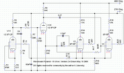
Well; you should ask SY, we observed one of my PP prototypes on his computer screen and saw -80 dB of 2'Nd order harmonic on power 40W (half a power). The rest was under the noise floor. Did I call it by some fancy merketing names like "WE compensation" or used other famous and well advertised name? No, I just called it an optimal engineering. Here is the driver schematic attached. It does not show output tubes and feedback resistors across them; and it does not show the global feedback loop from the secondary. Neither it shows MOSFET regulated power supplies.
Just one frame grid penthode stage, then Concertina that drives a LTP driver, and class AB output stage with local parallel resistive feedback by voltage from anodes. That's why quite power pentodes in LTP driver, to supply linear current swing to low input resistance of output stage.
Just one frame grid penthode stage, then Concertina that drives a LTP driver, and class AB output stage with local parallel resistive feedback by voltage from anodes. That's why quite power pentodes in LTP driver, to supply linear current swing to low input resistance of output stage.
Attachments
These kind of harmonic cancellation schemes usually work just for some low order harmonics (like 3rd, maybe 5th, for the WE HE), but likely mess up the higher ones. The compensation is never going to be exactly the inverse of the distorting function.
But if the higher order harmonics are already tailing off to begin with, then there are only low order ones left to fix. Just takes one tail resistor to see if its going to help or not. If one can minimize say the 5th H or 7th H by tuning the resistance, it could be useful.
To get more odd harmonics to converge/cancel over a wider range, one would likely need a non-linear tail resistance. Maybe a resistor and thermionic diode in series. One will need an army of Pixies to adjust each amplifier then. There is the 6JU8 with 4 6AL5 type diodes in the bottle. A jumper could select how many of them are used in series. And a variable CCS coming down from B+ could select the operating point (curvature) of the diodes. Probably will need to be re-tuned up every few months. If we had something like an analog EPROM (resistance function), computer tuned up at the factory.....
Last edited:
sser2: "IMD due to HD will not be compensated, it will be added."
If I'm following your argument here, you are saying that once the IM difference harmonics are generated in one stage, they cannot be removed in another stage by counter distortion?
This argument was famously battled by J. Ross MacDonald in some journal, (probably JAES) when he proposed a distortion cancellation scheme back in the 50s, I think. Turns out that you just have to get the end to end gain constant at all amplitudes and all is well. (assuming no freq. phase shifts or complex hysteretic type distortions) So some hope for gain compensation schemes. We really need something like an analog EPROM though. There used to be some adjustable analog function networks for analog computers using arrays of variable resistors and diodes. We would need like thousands of pots. (hence the need for an analog EPROM instead)
Last edited:
end to end gain constant at all amplitudes and all is well.
Yes, to re-phrase it, if an amp has no distortion, there will be no distortion. But i got the point, thanks.
Last edited:
When I played guitar, I made a pedal with diodes in feedback and a HPF, after that a couple of diodes in series, i.e. last diodes compensated non-linearities of first 2 in feedback, resulting in almost clean compression. Pushing the pedal I could smoothly go from almost no distortions to heavy overdrive. Later I found schematic of a Roland pedal that used similar approach, but without a pedal.
Yes, there is something in it...")
...for musical instruments.
Yes, there is something in it...
...for musical instruments.
With reference to the push pull WE 300B amp, it's not just adding a resistor to the tail of the LTP. One have to track the common mode even harmonic changes at the grid. The compensation from the tail resistor should only affect the plate voltage.
The difference is that adding a tail without the grid tracking it, is like a cathode degenerative feedback or local feedback using only the even harmonic common mode signal. If we think of a push pull output stage is actually made up of a balance amp and a single ended amp (which handle the unbalanced portion), then this local feedback should increase the plate impedance momentarily.
By tracking the common mode at the grid, the tail resistor is then equivalent to adding a resistor between B+ and CT of OPT.
- Status
- This old topic is closed. If you want to reopen this topic, contact a moderator using the "Report Post" button.
- Home
- Amplifiers
- Tubes / Valves
- Theory of Western Electric Harmonic Balancer explained