Hi all,
I'm currently reinventing the weel with different point of view on well known stuff.
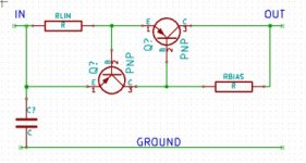
I would like to ask if anybody has ever used transistors as current limiters for screen grids, instead of the classical resistors.
The reason is that I like the dynamic that the amp has without screen resistors, but at the same time the tubes are really prone to blow.
So I thought about using current limiters to let the screen to see a very low resistance until the critical current is reached, then it is limited.
This should be a win-win solution, but evil is in details, and what I don't know is if anyone else has done similar tests, and what is the sonic reaction on transitories.
Has anyone some experience on it?
Thanks in advance for your help.
I'm currently reinventing the weel with different point of view on well known stuff.
I would like to ask if anybody has ever used transistors as current limiters for screen grids, instead of the classical resistors.
The reason is that I like the dynamic that the amp has without screen resistors, but at the same time the tubes are really prone to blow.
So I thought about using current limiters to let the screen to see a very low resistance until the critical current is reached, then it is limited.
This should be a win-win solution, but evil is in details, and what I don't know is if anyone else has done similar tests, and what is the sonic reaction on transitories.
Has anyone some experience on it?
Thanks in advance for your help.
Attachments
I guess the goal here is to limit screen dissipation power. While current limiter will achieve this, current limiting will cause screen voltage to drop. For best results, screen voltage in pentode connection should be kept constant.
With Ug2<<Ua, neither screen voltage regulation, nor screen dissipation is a problem, and screen power waste is minimized.
With Ug2<<Ua, neither screen voltage regulation, nor screen dissipation is a problem, and screen power waste is minimized.
I did it once. I thought it would be good protection for the output tubes in case of gross overload. I don't think there is any harm if you choose a screen current limit that won't be hit in normal operation.
One thing I did notice was that when I did a gross overload test, the waveform did look like a smoothed out volcano peak due to the screen voltage drop during current limiting. There was a point reached where if I drove the output tube harder, output would start to fall, then as the input signal reversed direction, output would begin to go back up, then back down. This was an open-loop amp but if this behavior were in a feedback loop, things might get weird/ugly.
I didn't think it was a problem for me in this open-loop amp because those were ear-bleeding power levels that would never be reached in normal practice but it is something to be aware of.
I played time ago an old Marshall 1959 without screen resistors and the feel was incredible. Due to a long tour, the player asked to install screen resistors, beause he was facing alot of blows on his EL34s. Done, then the feel was completly different. Removed again and back again the nice feel.I guess the goal here is to limit screen dissipation power.
Done on other amps, and the feeling is the same, but also the drawbacks.
Current reduced, series resistance increased, g2 voltage reeduced, gain reduced. Clear.One thing I did notice was that when I did a gross overload test, the waveform did look like a smoothed out volcano peak due to the screen voltage drop during current limiting.
With the right RC constants this can be musical in a tube amp. It can introduce compression. Have you tried to reduce the point where the current limiter starts working? This could become an interesting control.There was a point reached where if I drove the output tube harder, output would start to fall, then as the input signal reversed direction, output would begin to go back up, then back down. This was an open-loop amp but if this behavior were in a feedback loop, things might get weird/ugly.
Thanks, well noted.I didn't think it was a problem for me in this open-loop amp because those were ear-bleeding power levels that would never be reached in normal practice but it is something to be aware of.
With the right RC constants this can be musical in a tube amp. It can introduce compression. Have you tried to reduce the point where the current limiter starts working? This could become an interesting control.
I did not experiment much with it. I simply noted the waveform shape. Unfortunately, I didn't take a picture. My circuit had no RC time constants so recovered instantaneously.
I have tried strict current limiting on the screen supply of sweep tube amps since their screen grids are their weak point. A low enough current limit to avoid glowing grid syndrome on a cranked amp is audible on music with strong transients. This may not be the case with the usual audio tubes like 6L6GC, KT88, and EL34. I didn't try it with them.
Some type of VI limiting is required with screen driven sweep tubes to prevent catastrophic amp failure when the screen grid gets hot enough to emit electrons and cause a screen to plate tube arc, destroying the tube and most of the driver circuitry. I have been experimenting with something like what I describe below, only microprocessor controlled.
I have a little 4 watt push pull guitar amp that I designed and built. The output tubes are 32ET5's, common in the last generation of tube table radios. Their screen current goes up sharply as you slam the tubes into clipping, and this behavior is common with most tubes. After melting an output tube, I simply stuck a 2.7K (a 4 watt amp remember) resistor in series with the screen supply, and wired the entire preamp supply on the screen side of that resistor, for improved sag induced touch sensitivity and some degree of self limiting. Amp sounds great for a small practice amp.....done.
Some time later I wired two orange LED's and a 1K resistor in series and connected that string across the 2.7 K screen supply resistor. I mounted the LED's under the output tube sockets to create the illusion that the output tubes are melting when the amp is hammered hard. Cool effect, done.
It seems to me that the LED's could be attached to an LDR which could be used to shunt some of the drive signal to create a limiter device. I believe Wavebourne has done this on one of his stereo amps.
Some delay, or integration could be employed to allow quick transients to pass unlimited as to avoid interfering with the sound, but integrate up the long term screen input and reduce the average drive level or impose more strict limiting, before screen meltdown happens.
Then you will kill dynamics because screen current will be abruptly chopped all the time, same as poorly adjusted short protection in SS amps .... ugh !!!!!!The reason is that I like the dynamic that the amp has without screen resistors,
While a resistor has constant resistance and will be fr less intrusive.
What you need is a regulated screen supply, like sser2 said.
If you lower typical guitar amp abuse level voltage to what the datasheet suggests, say 350V for screens instead of tying it up to >>400V plate voltage, they will not suffer and being constant voltage, they won´t hurt dyamics.
I also built power amps using 6DQ6 sweep tubes, real robust and powerful but needed screens strictly kept at +150V , whuch was easy to do.
Way back then (we are talking the 70`s), no Mosfets available but I used high voltage TV sweep transistors, worked like a charm.
I played time ago an old Marshall 1959 without screen resistors and the feel was incredible. Due to a long tour, the player asked to install screen resistors, beause he was facing alot of blows on his EL34s. Done, then the feel was completly different. Removed again and back again the nice feel.
Done on other amps, and the feeling is the same, but also the drawbacks.
It is either poor sound or busted tubes - you pick your poison. As mentioned, this problem is specific for guitar amps, which are overdriven on purpose. There is no such problem in hifi, where amplifiers are used at only a fraction of their nominal power.
BTW, replacing screen resistors with a choke of appropriate DCR improves the sound while keeping protection afforded by the resistor.
When B+ is directly connected to screens (without screen resistors), screen voltage regulation is very good, hence good sound. However, when output swing increases, plate voltage at output signal peaks may drop well below B+. Electrons don't care whether it is plate or screen, they go to wherever potential is higher, that is to the screen. During these moments, screen will take most of the cathode current, causing its overheating and failure. You can enjoy precious moments of good sound though before your tubes go bust.
If you want low distortion then the screen grid needs to be fed from a low impedance source, usually a 1k resistor from a constant voltage supply (or the anode). The 1k is a compromise between distortion, protection and also acts as a grid stopper. Using a current limiter would not help because it will probably not act as a grid stopper (but could introduce its own parasitic problems) and will also be a source of unreliability. If you want low distortion then you will not overdrive the valves so the current limiter will have no effect anyway.
If you want a particular distortion effect then you can add whatever you like to your valves. A current limiter will cause peak distortion.
If you want a particular distortion effect then you can add whatever you like to your valves. A current limiter will cause peak distortion.
I believe you don't mean "constant current limit", if so it will not work.
Probably you can do better screen current limit using known sch published in the past, i.e using a diode to limit the current (flow one way, thereby reduce dissipation by half, AC impedance is low when conducts), and zener diode to adjust for appropriate screen voltage (usually lower than the plate voltage). I have done this in my 5-10W guitar amp, work in triode and pentode mode. It works, even zener is not bypassed as AC impedance is low when conducts. Omitting the diode still work but some pentodes screen will become red hot.
Pentodes & Tedrodes to Triodes
[JN] My little pentode-to-triode trick
Putting a diode in a screen supply is daft, yet surprisingly popular. If it conducts it does nothing. If it gets reverse biased it creates massive distortion. A piece of wire would be better.Koonw said:Probably you can do better screen current limit using known sch published in the past, i.e using a diode to limit the current (flow one way, thereby reduce dissipation by half, AC impedance is low when conducts),
Putting a diode in a screen supply is daft, yet surprisingly popular. If it conducts it does nothing. If it gets reverse biased it creates massive distortion. A piece of wire would be better.
I have 6p15p instead of 6p14p, it's screen got red hot. So I insert a diode in series, now 6p15p screen is normal (not red hot), difference if only a diode (forward biased) there or not. Maybe there is another explanation, DF?
- Status
- This old topic is closed. If you want to reopen this topic, contact a moderator using the "Report Post" button.
- Home
- Amplifiers
- Tubes / Valves
- Solid state current limiters instead of screen resistors